
Triac light driver

The circuit design for controlling room lighting via a computer employs triacs and opto-couplers to manage the AC load effectively. The triacs serve as electronic switches that can control high voltage and current, allowing for the operation of standard lighting fixtures. The opto-couplers isolate the low-voltage control signals from the high-voltage lighting circuit, ensuring safety and preventing interference.
The schematic features a connection from the computer's parallel port to the opto-couplers, which are activated by the digital signals sent from the PC. When a signal is received, the opto-coupler allows current to flow to the gate of the triac, triggering it to conduct and thus powering the connected lighting. The use of a 7805 voltage regulator ensures that the circuit receives a stable 5V supply, which is essential for the proper operation of the opto-couplers and any associated logic circuitry.
The 74LS06 hex inverting buffer is used to drive the opto-couplers, providing the necessary current to ensure reliable operation. The design allows for multiple lighting circuits to be controlled independently or in unison, depending on the configuration of the software running on the computer. Overall, this setup provides a flexible and efficient means of controlling room lighting, integrating seamlessly with existing computer systems.Controlling room lighting using computer. I bought some triacs and opto couplers to do this. I drew the schematic and built a prototype. Everything worked well. We cannot see it on the pictures, but there is a cable going out of the box that plugs in the PC parallel port. The small grey box on the leftmost picture contains a 7805 and a 76ls06 to driver the opto couplers. 🔗 External reference
Related Circuits
Operating high-beam headlights while driving on highways can significantly enhance visibility; however, it poses a blinding risk to other drivers. This straightforward circuit can be integrated into the headlight switch to facilitate automatic switching between high and low beam...
This project operates red, amber, and green LEDs in the correct sequence for a single UK traffic light. The duration of the complete sequence—red, red & amber, green, amber—can be adjusted from approximately 7 seconds to about 2.5 minutes...
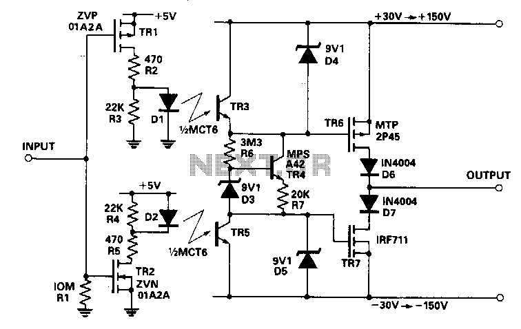
This circuit accepts a signal from a 5-V CMOS logic circuit and produces a high voltage of the same polarity. The high-voltage supply can be adjusted between ±30 V and ±150 V without requiring any changes to the circuit...
Flyback LED drivers are versatile as they can be utilized in applications with input voltages either above or below the necessary output voltages. They feature a straightforward circuit configuration that maintains a constant LED current without the need for...
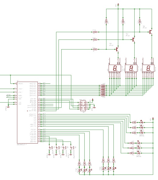
Learn to use microcontrollers to create traffic-light applications. In this project, the AVR-007 microcontroller from Circuits-Home will be utilized. Before developing the program, it is essential to understand the hardware specifications. The project focuses on developing a traffic-light control system...
A 2001 Chevrolet Cavalier has experienced a failure in one of the low beam headlights. Despite replacing the bulb, the headlight remains non-functional. Additionally, when the vehicle is shifted into gear, the daytime running lights flash multiple times before...