
triac light switch circuit
The described circuit operates on the principle of light sensitivity to control the brightness of the lamp. The primary component, the TRIAC, is a semiconductor device that can control power in AC circuits. When the LDR detects ambient light, it changes its resistance, which affects the gate trigger of the TRIAC. In bright conditions, the resistance of the LDR is low, preventing the TRIAC from conducting and thus keeping the lamp off or dim. Conversely, in low light conditions, the resistance of the LDR increases, allowing the TRIAC to trigger and turn on the lamp at a higher brightness level.
For optimal performance, the LDR should be positioned away from the direct light of the lamp it controls to ensure accurate light sensing. The variable resistor can be adjusted to fine-tune the sensitivity of the light detection, allowing for customization based on specific environmental lighting conditions. This flexibility makes the circuit suitable for various applications, such as automatic lighting control in homes or offices, where lighting needs may change throughout the day.
The overall design is efficient and cost-effective, making it an excellent choice for those looking to implement light-sensitive switching in their electrical systems. The simplicity of the circuit allows for easy assembly and troubleshooting, making it accessible for both novice and experienced electronics enthusiasts.The series of light switches this time slightly different from the stress of work. The series of light switches can work directly on the AC power network. Light switches are using the main component of TRIAC and LDR. The circuit is very simple and the components were sold in the market. If you want a light reception sensitivity of this circuit can be arranged then the 3. 3 MOhm resistor can be replaced with a variable resistor. For more details can be seen from the following series of images. Triac Light Switchcircuitseries is priciple work as dimers, but dimers of control carried out by the reception of light around the LDR. The lower the intensity cayaha received LDR then semkin bright lights. For installation LDR need to be considered so as not exposed to light from the lamp directly. 🔗 External reference
Related Circuits

This is an 80W power amplifier OCL circuit that utilizes the integrated circuit LM12. It effectively enhances bass and treble performance. When connected to a CD player, it produces high-quality sound, especially when paired with a good pre-tone control....
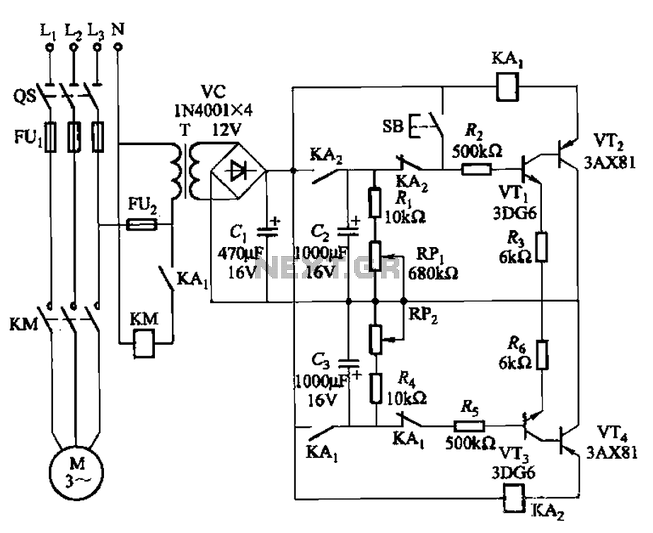
The circuit illustrated in Figure 3-79 consists of two delay circuits. The RPi adjustment potentiometer and RP2 can be modified to control the duration of the motor operation, allowing for arbitrary adjustments within a specified time frame. The circuit comprises...
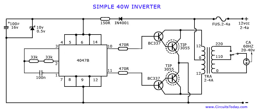
An article on how to create an inverter using a simple 40-watt inverter circuit diagram and schematics. This inverter converts 12 volts to 220 volts using the CD4047 integrated circuit. The described inverter circuit utilizes the CD4047 IC, which is...

A 750mW bridge-tied load audio amplifier circuit utilizing the LM4065 amplifier is presented below. The LM4865 is available in an 8-pin SO package and an 8-pin mini SMD package. The power supply voltage (VDD) ranges from 2.7V to 5.5V,...
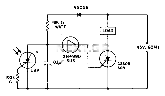
When the light incident on the LASCR is interrupted, the voltage at the anode of the 2N4990 unilateral switch becomes positive during the subsequent positive cycle of the power supply. This action triggers the switch and the C230 SCR...
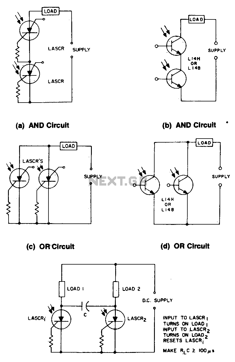
These circuits illustrate some of the common logic functions that can be implemented. The provided circuits serve as examples of fundamental logic functions utilized in digital electronics. Logic functions are the building blocks of digital systems, enabling the execution of...