
Intermittent start and stop cycle control circuit of the four
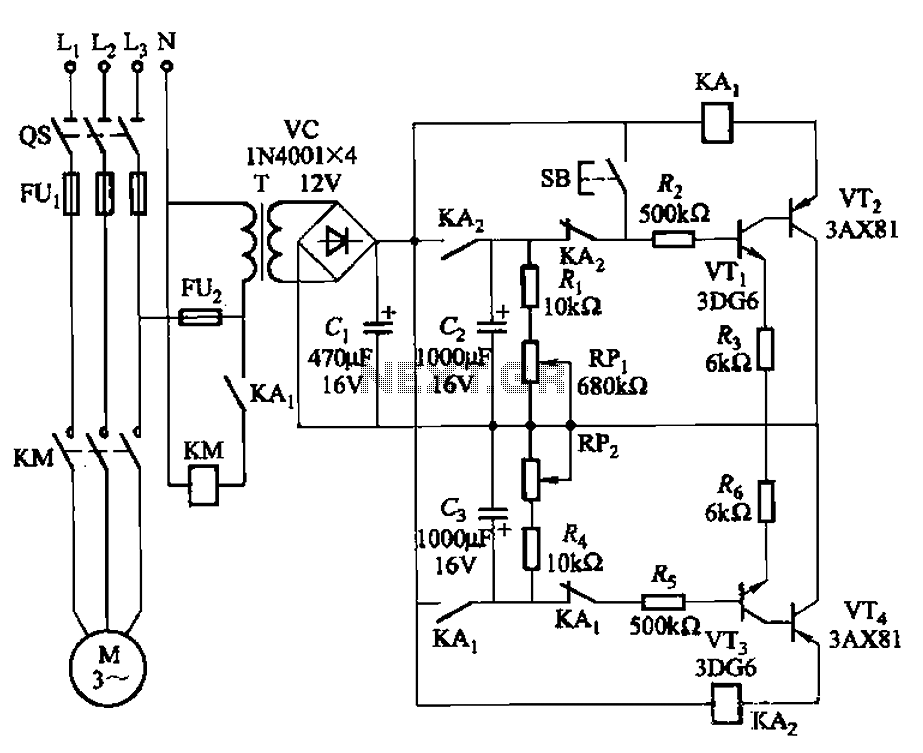
The circuit comprises two delay stages that serve to control the operation of a motor. The first delay circuit utilizes an RPi adjustment potentiometer, which allows for fine-tuning of the delay period. This component is crucial for setting the initial timing parameters that dictate how long the motor remains active before stopping. The second delay circuit, represented by RP2, further enhances the control over the motor's running time, providing additional flexibility in timing adjustments.
In practical applications, the use of potentiometers in delay circuits allows for user-friendly adjustments. By rotating the potentiometer knob, the resistance changes, thereby altering the time constant of the circuit. This results in a variable delay that can be tailored to meet the specific requirements of the motor operation. The timing can be adjusted within a defined range, making it suitable for various applications where precise motor control is necessary.
The integration of these delay circuits ensures that the motor can be activated or deactivated based on the desired timing, enhancing efficiency and functionality in automated systems. Additionally, the circuit design may include other components such as capacitors and transistors, which work in conjunction with the delay circuits to stabilize the operation and enhance the performance of the motor control system. Overall, the schematic provides a robust solution for controlling motor operations with adjustable timing capabilities. Circuit shown in Figure 3-79. It consists of two delay circuits, respectively. RPi adjustment potentiometer and RP2, respectively, can be changed and stop the motor running the length of time (arbitrarily changed within th).
Related Circuits
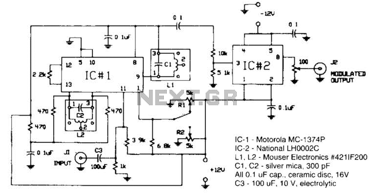
Circuit for applying a DC-coupled FM or PPM to a 555 configured as an oscillator. IC-1 is a Motorola MC-1374P, and IC-2 is a National LH0002C. L1 and L2 are Mouser Electronics #421IF200. C1 and C2 are silver mica...
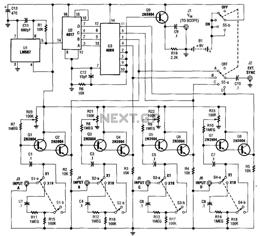
This simple adapter utilizes an oscillator (567) to drive a counter (U2) and a switch (U3) that selects the output of one of four scope preamps (Q1/Q2 through Q7/Q8) and feeds it to buffer Q9 and output jack J1....
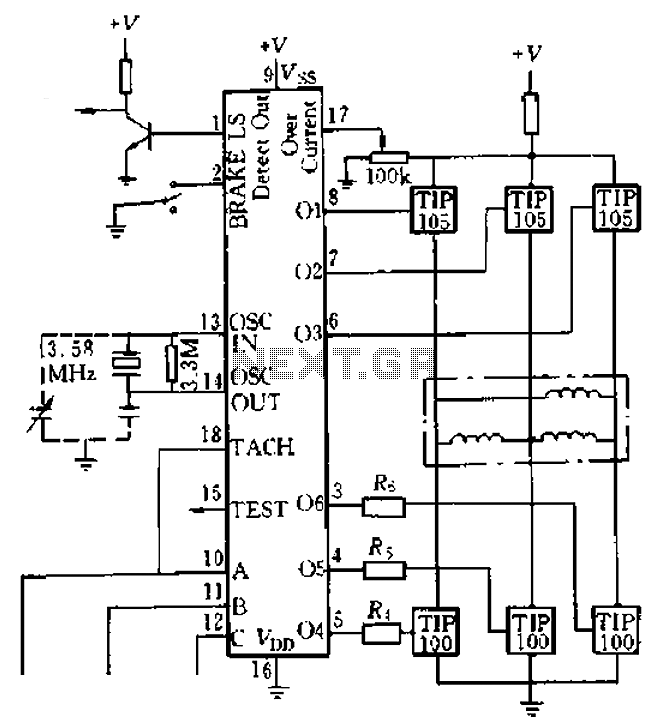
Four application examples are presented in the figure, focusing on a three-phase brushless DC motor used in Winchester disk drives with an operating speed of 3600 RPM. Although the original design specifies an operating speed of 3600 RPM, alternative...
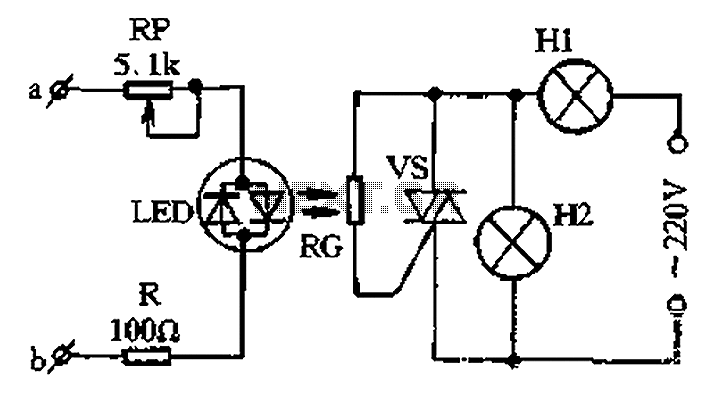
The circuit for a two-color music lantern controller is illustrated in Figure 1-44 below. Terminals a and b are located at both ends of the speaker, which receives audio signals. The audio signal is processed through a sensitivity adjustment...
This page presents a circuit featuring twenty open collector outputs that activate sequentially in a continuous, unidirectional loop. The circuit utilizes the 74LSxx family of TTL integrated logic devices. It is designed to drive light-emitting diodes or low current,...
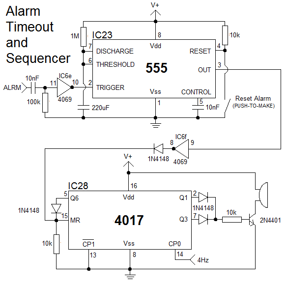
The clock is constructed using 25 CD4000 integrated circuits (ICs), three 555/556 ICs, and several discrete components. It features an alarm and a method for setting the time that is typically only seen in microcontroller designs. The complexity of...
Warning: include(partials/cookie-banner.php): Failed to open stream: Permission denied in /var/www/html/nextgr/view-circuit.php on line 713
Warning: include(): Failed opening 'partials/cookie-banner.php' for inclusion (include_path='.:/usr/share/php') in /var/www/html/nextgr/view-circuit.php on line 713