
How to make an Inverter-Simple 40 Watts Inverter Circuit
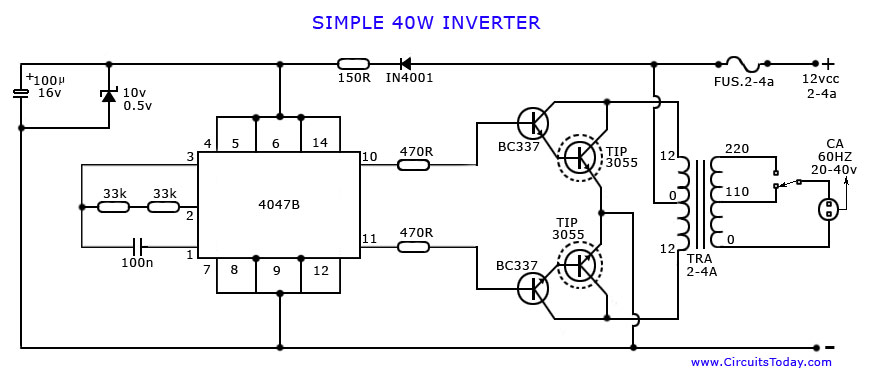
The described inverter circuit utilizes the CD4047 IC, which is a versatile component capable of functioning as either an astable multivibrator or a monostable multivibrator. In this application, the IC operates in astable mode to generate a square wave output that is essential for driving the inverter's power stage.
The circuit typically consists of several key components: the CD4047 IC, a transformer, capacitors, resistors, and a power transistor or MOSFET. The 12-volt input is fed into the CD4047, which produces a square wave output at a frequency determined by the external resistor-capacitor (RC) network connected to its timing pins. This output is then fed into the primary winding of a transformer, which steps up the voltage to the desired 220 volts AC.
To ensure proper operation, the circuit should include filtering capacitors to smooth out any voltage spikes and protect the components from high-frequency noise. Additionally, the transformer must be rated appropriately for the expected load, with a sufficient turns ratio to achieve the necessary voltage conversion.
The power stage may involve a push-pull configuration using transistors or MOSFETs to efficiently switch the current through the transformer, ensuring that the inverter can deliver up to 40 watts of power. Proper heat dissipation measures, such as heat sinks, should be employed to prevent overheating of the power devices.
Overall, this inverter design provides a practical solution for converting low-voltage DC power to high-voltage AC power, suitable for a variety of applications, including powering small appliances and electronic devices.An article on How to make an inverter using simple 40 Watts inverter circuit diagram and schematics. This is a 12 volts to 220 Volts inverter using CD4047 IC.. 🔗 External reference
Related Circuits
Free energy motors and generators are available for purchase, featuring plans for overunity devices. These devices resemble oscillators used in Joule thief circuits, although there may be some errors present in the designs. However, the concept remains clear. Free energy...
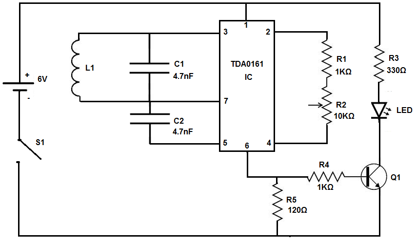
The device being constructed will serve as a metal detector, capable of locating metal objects such as coins, nails, and keys, including car keys that may be misplaced. It can also detect gold, although it may not possess industrial...
Have you ever attempted to copy a commercially produced video only to end up with a distorted and jumpy image? If so, then you have run afoul of MacroVision. MacroVision is the most popular copy protection scheme used on...
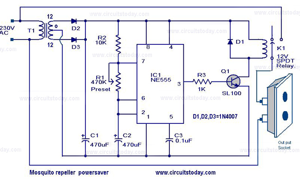
The circuit diagram of a mosquito repellent power saver circuit is provided along with a detailed explanation. The mosquito repellent power saver circuit is designed to efficiently operate a mosquito repellent device while minimizing energy consumption. This circuit typically integrates...
The welder no-load power saver circuit consists of a current detection control circuit and a power saving control circuit, as illustrated in the accompanying chart. The current detection control circuit includes a current transformer (TA), a bridge rectifier (UR),...
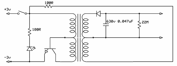
This simple circuit is started running by connecting a twelve volt battery across the terminals, causing the large diameter Light-Emitting Diode to light up. When the battery is removed, the LED stays lit up because the circuit has become...
Warning: include(partials/cookie-banner.php): Failed to open stream: Permission denied in /var/www/html/nextgr/view-circuit.php on line 713
Warning: include(): Failed opening 'partials/cookie-banner.php' for inclusion (include_path='.:/usr/share/php') in /var/www/html/nextgr/view-circuit.php on line 713