
Triple Emitter-Follower as OPS for the Aikido

The hybrid amplifier design integrates two distinct amplification stages to achieve high performance and efficiency. The Aikido topology, known for its low distortion and high linearity, serves as the voltage amplification stage. This configuration typically employs a differential amplifier followed by a push-pull output stage, which helps in maintaining a balanced operation and reducing common-mode noise.
The output stage, implemented as an emitter-follower, is chosen for its high current drive capability and low output impedance. This configuration allows the amplifier to effectively drive loads while maintaining signal integrity. The emitter-follower stage provides voltage buffering, which is crucial for interfacing with subsequent stages or speakers without significant signal degradation.
In designing this hybrid amplifier, careful consideration must be given to the biasing of the Aikido stage to ensure optimal performance. The use of feedback mechanisms can further enhance linearity and stability across varying load conditions. Additionally, the power supply design should accommodate the requirements of both stages, ensuring that adequate voltage and current are supplied without introducing noise into the system.
Thermal management is another critical aspect, as both the Aikido and emitter-follower stages can generate heat during operation. Implementing proper heat sinking and ventilation strategies will help maintain the reliability and longevity of the amplifier.
Overall, this hybrid amplifier design aims to combine the strengths of both the Aikido and emitter-follower configurations, resulting in a high-fidelity audio amplification solution suitable for various applications.Hi, I`m working towards an hybrid amplifier where the VAS will be the Aikido, where the OPS is some Emitter-Follower variation. Unfortunately my.. 🔗 External reference
Related Circuits
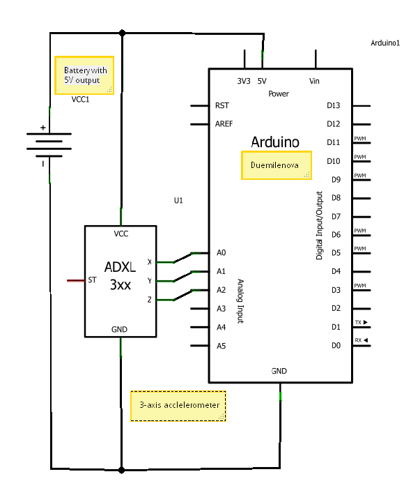
A circuit diagram illustrating the connection of an accelerometer to an Arduino board and an external power source. The circuit diagram depicts the integration of an accelerometer with an Arduino microcontroller, providing a clear representation of how these components interact...
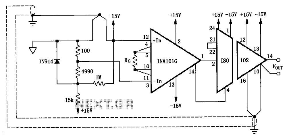
The circuit, as illustrated in the figure, consists of an ISO102 and an INA101 designed to eliminate ground loops and provide high-end cold junction compensation for a thermocouple amplifier. This configuration utilizes a K-type thermocouple to detect temperature at...

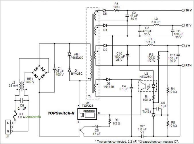
Design a low-cost 4- to 20-mA receiver circuit for control loops using an analog-to-digital converter (ADC). The design of a low-cost 4- to 20-mA receiver circuit is essential in industrial applications for monitoring and controlling processes. This current loop standard...

This circuit allows for the observation of movement between various stroboscopes. The generation of a rectangular signal is accomplished using an NE555 timer. It operates on a low power supply, which is created using a simple transformer (TR1), a...
This application note describes a digital blood pressure meter concept that utilizes integrated pressure sensor analog signal-conditioning circuitry, microcontroller hardware/software, and a liquid crystal display. The sensing system measures cuff pressure (CP) and extracts pulses for analysis to determine...
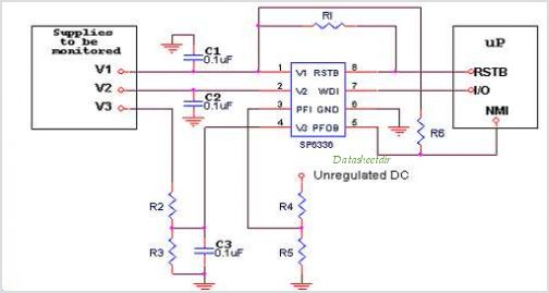
Introduction The SP6648 integrated synchronous boost regulator is a compact circuit that provides ultra-high efficiency drive current for an LED flashlight using a Luxeon I light source. The circuit is configured to deliver a constant output current of 350mA...