
task 32 triple axis accelerometer
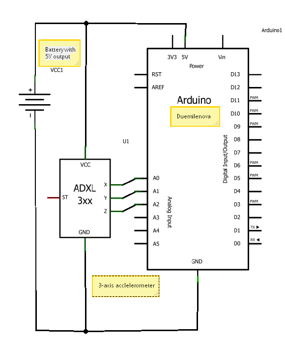
The circuit diagram depicts the integration of an accelerometer with an Arduino microcontroller, providing a clear representation of how these components interact within an electronic system. The accelerometer, a device that measures acceleration forces, is connected to the Arduino board, which serves as the central processing unit for data collection and processing.
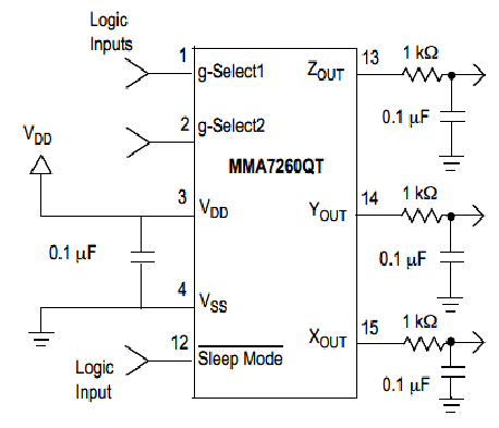
In this setup, the accelerometer typically has three output pins corresponding to the X, Y, and Z axes of acceleration. These pins are connected to the analog input pins of the Arduino board, allowing the microcontroller to read the acceleration data. The external power source is essential for powering both the accelerometer and the Arduino, ensuring that the circuit operates efficiently.
The power connections are usually made by connecting the VCC pin of the accelerometer to the positive terminal of the external power source, while the GND pin is connected to the ground. This configuration ensures that the accelerometer receives the necessary voltage for proper operation.
In addition to the basic connections, pull-up or pull-down resistors may be included in the schematic to stabilize the signal levels and prevent floating inputs. Capacitors can also be integrated into the circuit to filter out noise and provide a stable power supply to the components.
Overall, this circuit diagram serves as a fundamental illustration for those looking to utilize an accelerometer with an Arduino platform, facilitating various applications such as motion detection, tilt sensing, and gesture recognition.a circuit diagram showing how the accelerometer is connected to an Arduino board & external power source (not complicated at all, is it) 🔗 External reference
Related Circuits
Microcontroller-Based Accelerometer Project. Just as a speedometer is a device that measures speed, an accelerometer is a device that measures acceleration. The microcontroller-based accelerometer project utilizes an accelerometer sensor to detect changes in velocity and orientation. This project typically involves...
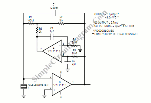
An inverting mode amplifier is required for precision accelerometers due to their typical charge output characteristics. This amplifier is utilized to convert charge into voltage. An inverting mode amplifier is a critical component in applications involving precision accelerometers, which often...

A hybrid amplifier is being developed, utilizing an Aikido configuration for the voltage amplification stage (VAS) and an emitter-follower variation for the output stage (OPS). The hybrid amplifier design integrates two distinct amplification stages to achieve high performance and...
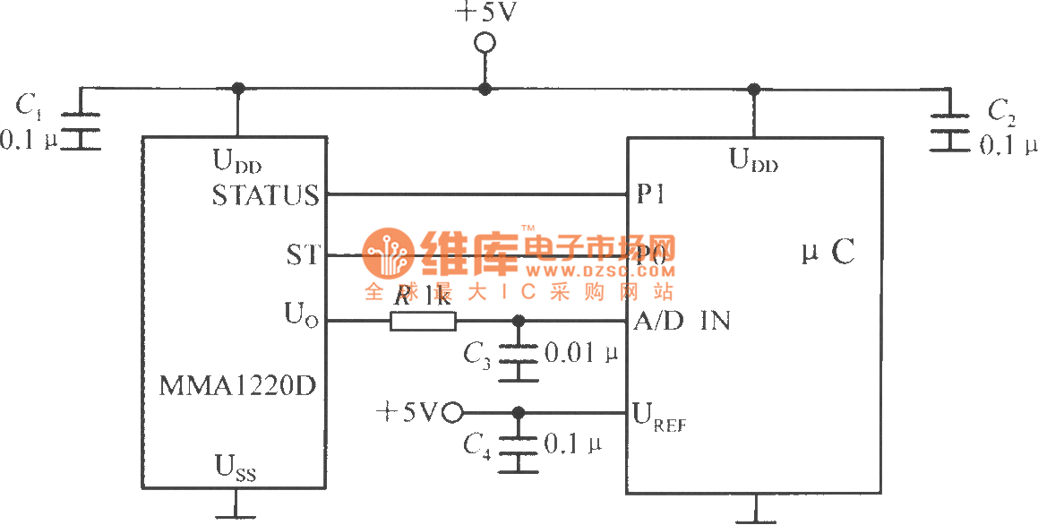
The microcontroller within the A/D converter can utilize a PIC MCU produced by Microchip. The MMA1220D's state and self-test pins are connected to the P1 and P0 ports of the microcontroller, with its output voltage sent to the input...
Each grid is biased to cutoff, allowing the mixer to accept only positive-polarity pulses with sufficient amplitude to overcome this bias. -NBS, "Handbook Preferred Circuits Navy Aeronautical Electronic Equipment," Vol. 1, Electron Tube Circuits, 1963, p N4-2. In a typical...
.jpg)
This is a two-phase hybrid stepping motor with a dynamic voltage range of 12 to 48V and a maximum current rating of less than 5A. The motor has an outer diameter ranging from 35 to 86 mm. The drive...