
Triple Stroboscope Circuit

The described circuit is designed around the NE555 timer IC, which is widely used for generating precise timing pulses and oscillations. In this application, the NE555 is configured in astable mode, allowing it to produce a continuous square wave output. The frequency of the output signal can be modified by adjusting the resistance of potentiometer P1, which alters the charge and discharge times of the timing capacitor connected to the NE555.
The power supply for this circuit is derived from a transformer (TR1), which steps down the voltage from the mains supply. The AC voltage output from the transformer is then rectified using a traditional bridge rectifier configuration, converting it to a DC voltage. To ensure stable operation and to protect the circuit from voltage spikes, a Zener diode is incorporated into the power supply design. This diode regulates the voltage and provides a consistent operating voltage for the NE555 timer.
The ability to place the control potentiometer P1 up to 30 meters away from the circuit allows for flexibility in the setup of the stroboscope. This feature is particularly useful in applications where the stroboscope needs to be suspended or positioned at a distance for optimal observation of movement. The remote adjustment capability enhances user convenience and operational efficiency, enabling precise control over the stroboscopic effect without the need for direct access to the circuit.
Overall, this circuit is an effective solution for generating stroboscopic effects and observing movement, combining ease of use with reliable performance.This circuit enables observation of movement between other stroboscopes. Generation of rectangular signal is based on NE555. This circuit requires a low power supply that is made from a simple transformer TR1, traditional rectifier bridge and zener diode. The frequency is adjusted by potentiometer P1. The control potentiometer P1 can be placed as far as 30 meters away, for suspension of stroboscope ½s work from far away. 🔗 External reference
Related Circuits

1. Abstract Wet-garden is an interactive flower garden and an ambient indoor sculpture. When people walk around it, it changes motion and LED blinking speed. Wet-design is designed for everyone who wants a tangible interaction object and an interesting...

EL auxiliary lights. When the lights dim in the ballroom, EL automatic lights, and ballroom lights dim in a more serious manner. EL light becomes brighter, allowing the inner disco lighting to automatically maintain a certain brightness. A photoresistor...
This is a solar tracking circuit designed to harness power from sunlight. The circuit operates optimally by maximizing sunlight exposure to generate electricity. The solar tracking circuit utilizes a combination of photovoltaic (PV) cells, sensors, and a microcontroller to adjust...

This circuit features a three-wire serial interface for smart temperature sensors, specifically the DS1620, along with an SPI bus interface circuit. The DS1620 is a high-accuracy digital temperature sensor that communicates over a three-wire interface, which consists of a data...
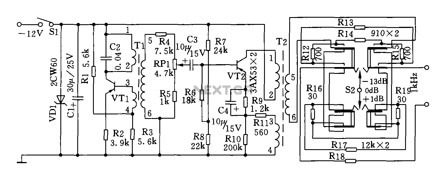
This circuit can generate a signal of 1 kHz and offers three output level options. It is suitable for testing communication equipment maintenance and barriers, providing a quick and accurate method to identify points of failure in televisions, stereos,...

The circuit depicted in the figure features the ISO102 and XTR101 components, forming an isolated remote transmitter circuit equipped with isolated thermocouple cold-junction compensation. The circuit comprises four main parts: the current loop amplifier XTR101, the isolation amplifier ISO102,...