
Triple Spring Reverb
The spring reverberation unit features three identical sections, each housing an Accutronics type 9 spring reverb tank, which are designed to provide varying decay times: short, medium, and long. The architecture of the circuit includes controls for adjusting the levels of both the dry (unprocessed) and wet (processed) signals, allowing for a customizable reverb effect. The feedback control mechanism is a critical component, enabling the output from the spring tank to be routed back into the tank input, which generates oscillation effects that can enhance the auditory experience.
The output from each spring tank is made accessible via a dedicated socket for further processing through other effects units. An insert input socket is included, which allows for returning processed signals from external effects. This insert function takes precedence over the tank output, ensuring that any effects applied are integrated into the feedback loop of the tank, thereby enabling advanced sound manipulation such as frequency shifting for dynamic reverb effects.
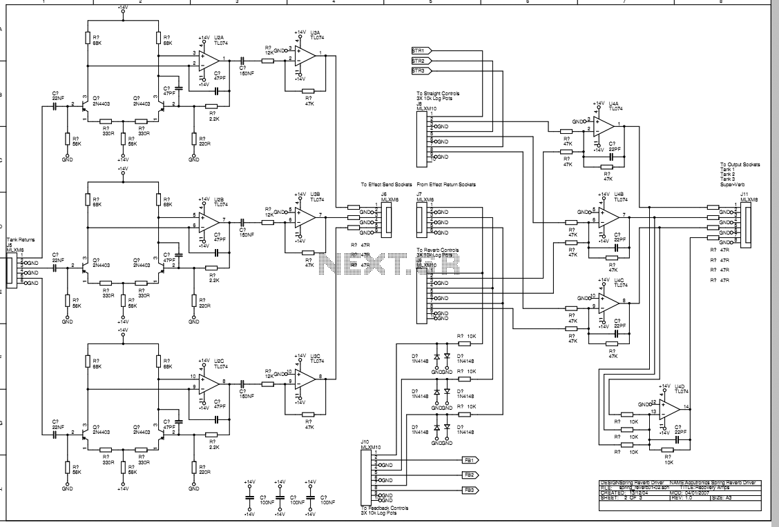
The drive circuits for the tanks are implemented using class B amplifiers, which are driven by outputs from a TL074 operational amplifier. Each tank's input transducer connects to ground through an 8.2 Ohm resistor, which plays a crucial role in shaping the frequency response by transforming the primarily inductive nature of the tank transducer into a more resistive load. The operational characteristics of the tank are such that at 1 kHz, the impedance is approximately 10 Ohms, allowing for a predictable current flow that decreases at a rate of 6 dB per octave above this frequency.
The feedback configuration for the op-amp driver is designed to maintain a constant current output, which compensates for the rising impedance of the tank transducer at higher frequencies. However, the circuit is engineered to roll off the drive current beyond approximately 7 kHz to avoid unnecessary power dissipation and maintain stability, despite the phase shifts introduced by the inductive load.
The output section incorporates low-noise pre-amplifiers and voltage gain stages, utilizing a dual PNP transistor differential input configuration with feedback from an op-amp. This arrangement is optimized for minimal noise at a nominal input impedance of 2 kOhms. High-pass filtering is achieved through a combination of input capacitors and bias resistors, effectively removing unwanted low-frequency noise. The frequency response is further managed by capacitors that work in conjunction with the tank's impedance to limit noise bandwidth and define the upper cutoff frequency.
To mitigate the risk of excessive feedback and potential damage to the tank transducers, diode limiters have been strategically placed after the feedback control pots. This addition ensures that while the system can achieve rapid feedback build-up for resonant effects, it simultaneously prevents signal levels from reaching damaging thresholds, thereby enhancing the reliability and longevity of the unit.This spring reverberation unit comprises three identical main sections each of which contains an Accutronics type 9 spring reverb tank with short, medium and long decay times. Controls are provided to adjust the amount of signal arriving at the output from the input directly and from the spring tank.
Conventionally these signals are called "dry" and "wet." A feedback control allows the tank output to be returned to the tank input to produce oscillation effects. The amplified output from the spring tank is available on a socket to send to other effects units and an insert input socket is provided for the return from that effect.
The insert socket overrides the signal from the tank output. This return is prior to the feedback control so that the effects unit is within the tank feedback loop. In this way a frequency shifter could be used in the send-return loop to provide rising or falling reverb effects.
The Accutronics type 9 is the best unit made by that manufacturer and is considered to be a high quality spring reverb used in many respected products. This sheet shows the three tank drive circuits. These are simple class B drivers driven from the TL074 outputs. The ground side of the tank input transducers returns to ground via an 8.2Ohm resistor. This provides the first stage of frequency response shaping by making the mainly inductive tank input transducer look more resistive. The tank has an impedance of approximately 10Ohms at 1KHz which is mostly inductive. With the 8.2Ohm resistors the current in the tank driver will be about -3dB at 1KHz and reducing at approximately 6dB per octave above that frequency.Taking the feedback for the op-amp/driver combination from the top of this resistor makes the driver a constant current circuit, so the output swing will increase as the impedance of the tank transducer rises at higher frequencies.
This continues up to a certain frequency defined by the capacitor in the feedback circuit. The current drive is rolled off above about 7kHz as the tank mechanical response rolls off rapidly much above 6kHz. Extending the drive bandwidth higher would be useless and result in lots of unnecessary current circulating around the circuit at 15 or more kHz.
Stability of the circuit is very good despite the phase shift created by the inductive load above 1kHz. This circuit requires the use of the tank version with isolated input transducers. Using this circuit with the sense resistor grounded also allows for easy single-ended measurement of the drive current.
This sheet shows the low noise pre-amp circuits for the tank output transducers, voltage gain stages and the output socket drivers and summers. The dual PNP transistor differential input stages with the op-amp feedback are a standard circuit with the operational currents set to minimise noise at the nominal input impedance of 2kOhms.
The 100nF input cap and the dominant 22kOhm bias resistor form a high pass filter to eliminate deep bass rumble from vibrations in the spring tank. The 2.2nF input cap reacts with the tank impedance to roll off the frequency response above 8kHz and to limit the noise bandwidth.
Gain is set by the op-amp feedback divider which is low impedance to reduce noise in the feedback transistor. The input amplifiers are a.c. coupled into a further op-amp stage which brings the signal back to the level at which it entered the front panel input sockets.
This is presented at the effect send sockets. While using the unit I found that the reverb controls produced a useful effect but it was very easy for the feedback to build up to a point where the oscillation level was very high and clipping excessively. This was risking possible damage to the tank input transducers and so subsequently I have added simple diode limiters after each of the feedback control pots.
With a small adjustment to the subsequent gain setting feedback resistors, there is still enough gain round the loop to ensure a swift build-up to a feedback oscillation, but the excessive signal levels are avoided. 🔗 External reference
Related Circuits
The Tri-Waveform Generator can be used for a number of different uses. The one that I use it for is a signal generator to test circuits. The frequency range is 20 to 20kHz and can be adjusted by R1....
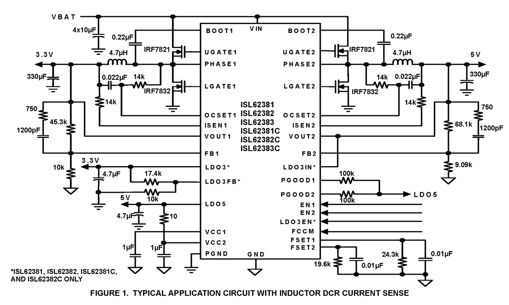
The ISL62381, ISL62382, ISL62383, ISL62381C, ISL62382C, and ISL62383C family of controllers generate supply voltages for battery-powered systems. These controllers include two pulse-width modulation (PWM) controllers, adjustable from 0.6V to 5.5V, and two linear regulators, LDO5 and LDO3, that generate...
This circuit was inspired by a friend who wanted a reverb for his portable guitar amplifier. I originally tried using NE5532 low noise op-amps for the buffer stages but they were too noisy for the low level circuits so...
The first reverberator presented is based on the TDA1022, which is the most commonly used BBD (Bucket Brigade Device). Adjustments for proper functionality of the reverberator are required before connecting the power supply. The TDA1022 is a versatile BBD that...
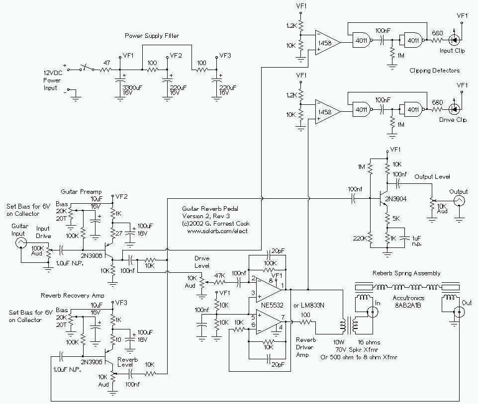
This is my second-generation guitar reverb circuit. The fidelity is much improved over the earlier design, it is suitable for use as a front-end to a guitar amplifier. This circuit features clipping indicators on the preamp and reverb recovery...

The guitar input stage is a class A amplifier with adjustable bias. A 2N3906 PNP transistor is used for a low noise design on this stage. The output of the preamp stage is sent to three places: the output...