
Triple Waveform Generator with 8038

The Tri-Waveform Generator is a versatile electronic circuit designed to produce three types of waveforms: square, triangular, and sine waves. This generator is particularly useful for testing and troubleshooting electronic circuits, providing a reliable source of signals across a frequency range of 20 Hz to 20 kHz.
The frequency of the output waveforms can be finely tuned using a variable resistor labeled R1. By adjusting R1, the user can set the desired frequency within the specified range, allowing for flexibility in testing various circuit responses to different signal frequencies.
Additionally, the duty cycle of the square wave output can be modified using another variable resistor, R4. The duty cycle defines the proportion of time the waveform remains high (active) versus low (inactive) within one complete cycle. This feature is critical for applications where specific timing characteristics are required, such as in pulse-width modulation (PWM) applications.
To ensure the integrity of the sine wave output, which is often used for more sensitive applications, R2 and R3 serve as distortion correction components. These resistors are adjusted while monitoring the sine wave output on an oscilloscope. The oscilloscope allows the user to visualize the waveform and make precise adjustments to R2 and R3, minimizing any harmonic distortion and achieving a clean, accurate sine wave output. This adjustment process is essential for applications that require high fidelity in signal reproduction.
In summary, the Tri-Waveform Generator is an essential tool for electronics testing, providing adjustable frequency, duty cycle control, and distortion correction capabilities to ensure a versatile and reliable signal generation.The Tri-Waveform Generator can be used for a number of different uses. The one that I use it for is a signal generator to test circuits. The frequency range is 20 to 20khz. and can be adjusted by R1. The duty cycle or the time that the waveform is high and the time that the waveform is low can be adjusted by R4. The purpose of R2 and R3 are to clean up any distortion on the sine wave output. To do this you must hook up the sine wave output to and oscilloscope and adjust R2 & R3 to make the sine wave as accurate as possible.
🔗 External reference
Related Circuits
The linear charging ramp is particularly beneficial in applications requiring precise linear voltage control. Potential uses include a prolonged voltage-controlled timer, a voltage-to-pulse-width converter, or a linear pulse-width modulator. Q1 functions as the current source transistor, delivering a constant...
This two-transistor white noise generator exhibits approximately 30 dB more noise than traditional designs. Transistors Q1 and Q2 can be any small-signal transistors with a beta rating of up to 400. The reverse-biased emitter-base junction of Q1 serves as...
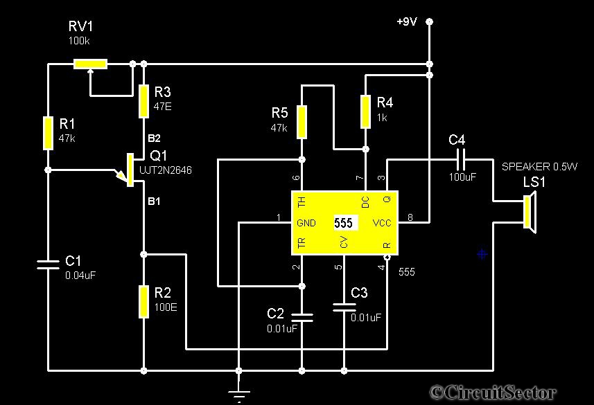
The circuit diagram illustrates a timer 555-based rain sound generator. It requires a 9V DC power supply, which can be provided by a 9V battery. The circuit utilizes a 0.5W, 8-ohm speaker to produce sound. When powered by a...
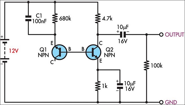
This simple circuit generates a good and stable 1V peak-to-peak square wave at 100Hz, 1KHz and 10KHz using a single 1.5V cell as power supply. An useful feature of this circuit is that frequency changes can be obtained by...
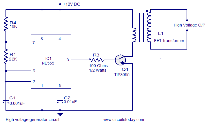
This circuit is highly dangerous due to its output voltage, which is in kilovolts and poses a significant risk of serious injury or death. It should only be attempted by individuals with extensive experience in handling high voltages. No...
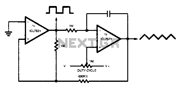
The output range varies precisely from rail to rail, making the frequency and duty cycle nearly independent of power supply variations. The circuit in question is designed to operate with a wide output range that spans from the minimum to...