
Tube Headphone Amplifier ECC86
This description outlines a triode amplifier circuit based on the EarMax Pro design utilizing ECC86 vacuum tubes. The ECC86 is particularly suited for this application, originally designed for front-end car radios, and operates effectively at an anode voltage of 6V DC, although the circuit is designed for a higher anode voltage range of 48 to 60V, which is considered safe and manageable for less experienced hobbyists.
The circuit is constructed without a printed circuit board (PCB), making it accessible for DIY enthusiasts. The use of a ferrite bead (L1) connected to R1 is critical for radio frequency (RF) suppression, ensuring that the amplifier operates within a frequency range of approximately 20 Hz to well above 1 MHz. Only one channel of the amplifier is described, with a note that the other channel is identical, requiring an additional ECC86 tube for full stereo operation.
The parts list provided includes various resistors and capacitors, all chosen for their specific electrical characteristics suitable for audio amplification. The resistors are primarily 0.6 W metal film types, ensuring precision and stability in the circuit. Capacitors include 22µF and 100nF ceramic types, which are chosen for their reliability and performance in audio applications. The volume control is implemented using a logarithmic potentiometer rated at 100k ohms.
Overall, this amplifier design is straightforward, emphasizing ease of construction and operation while providing high-quality audio output through the use of vacuum tube technology.Because it seemed fun to me also try the so-called "high-end tube technique to highlight here, I agree with some parts from the stock went to work. A second point was that my family had enough of my taste in music that boomed through the speakers. Opted for a triode circuit, based on EarMax Pro, ECC86's. This is a tube that had been designed as a front-end car radios in the serve. With an anode voltage of 6V DC ECC86 still works fine. This design is chosen for an anode voltage of 48 to 60V. This is a safe voltage. Also for less experienced hobbyists. The setup is straightforward, without print, and everyone should be doing. L1 is a ferrietkraaltje connection to a leg of R1. This is necessary for the required RF suppression. The frequency range is ± 20Hz to well above 1MHz. Described only one channel. The other channel is identical and there is an extra ECC86 badly needed. Power for this amplifier is described separately under the heading power. Parts List: R10 = 33 ohm R9 = 150 ohms R6, R7, R8 = 470K ohm R3 = 12k ohm R1, R4 = 220 ohms R2 = 1M ohm R5 = 1k ohm R11 = 22k ohm All resistors 0.6 W metal film C2, C8 = 22? 63V C3, C5 = 22n MKM 1000? C9 = 63V C1, C4, C7, C10, C11 = 100n ceramic C6 = 220? 63V V1a, V2a / b = 2 x 86 ECC P1 = 1 x 100k log. L1 = R1 ferietkraal to leg 🔗 External reference
Related Circuits
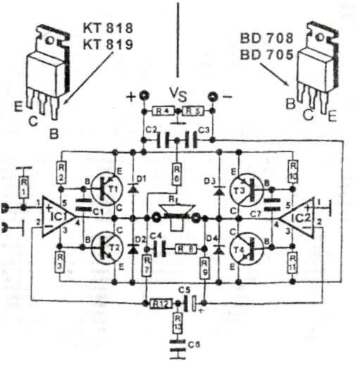
This audio amplifier circuit provides up to 200 W of high-quality output for loudspeakers with impedances ranging from 4 to 16 ohms. The operating voltage is between 24 and 36 V, with a maximum current of 5 A. The audio...
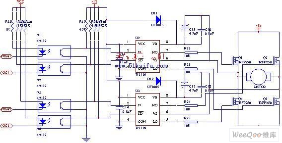
The drive circuit for the electromotor comprises a FET bridge circuit, a FET base drive circuit, a current sensor for the motor drive circuit, and a relay. The FET bridge circuit primarily consists of four high-power MOSFETs, which must...
A simple preamplifier circuit is often required, utilizing a few components for ease of construction. This circuit employs an operational amplifier, specifically the Motorola TCA5550, which features a dual amplifier configuration. It provides outputs for adjusting volume, balance, treble,...
Stereo tube amplifier circuit built with 5 power tubes: 6SQ7-GT, 6V6-GT, and 5Y3-GT. This circuit generates up to 4 watts of audio output per channel. The stereo tube amplifier circuit utilizes a combination of five power tubes, specifically the 6SQ7-GT,...
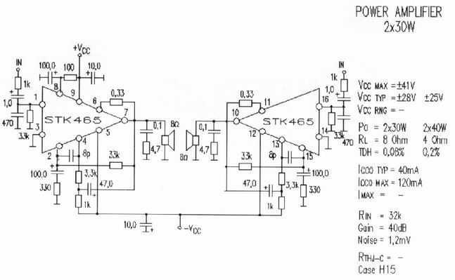
Completed STK465 is an amplifier of acoustic frequencies that offers qualitative output, using minimal exterior elements. Substantially he is one of big completed force. Has a line pins and incorporated metal surface for adaptation in cooler. The provision pins...
The circuit was designed to produce a preamplifier with symmetrical audio input while the output operates in Class A type. Preamplifier (pre-amp) a device... The circuit in question is a preamplifier designed to handle symmetrical audio inputs, which ensures that...