
200W Transistor Audio Amplifier Circuit
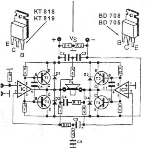
The audio amplifier circuit is designed to deliver robust power output while maintaining high fidelity, making it suitable for a variety of audio applications. The amplifier's power output of 200 W allows it to drive loudspeakers effectively, ensuring clear and dynamic sound reproduction. The impedance range of 4 to 16 ohms provides flexibility in speaker selection, accommodating a wide range of loudspeaker configurations.
The circuit operates within a voltage range of 24 to 36 V, which is essential for achieving the desired power output without distortion. A maximum current rating of 5 A ensures that the amplifier can handle the load presented by the connected loudspeakers without overheating or failing.
The design of the amplifier typically includes components such as transistors or integrated circuits that are capable of handling high power levels. Additionally, proper heat dissipation mechanisms, such as heat sinks or fans, may be incorporated to maintain optimal operating temperatures during extended use.
Input and output connections are designed to minimize signal loss, and filtering components may be used to eliminate unwanted noise and enhance audio quality. Overall, this audio amplifier circuit is well-suited for high-performance audio systems, providing the necessary power and quality for an immersive listening experience.This audio amplifier circuit delivers up to 200 W of top-class quality for loudspeaker from 4 to 16 ohm. Operating voltage is between 24 and 36 V, max 5 A 🔗 External reference
Related Circuits
Even if simple, the circuit meets all conditions regarding distortion and frequency response. The input resistance is 250K ohms, and it can drive loads between 100 ohms and 2K ohms. The described circuit is a basic signal processing circuit designed...
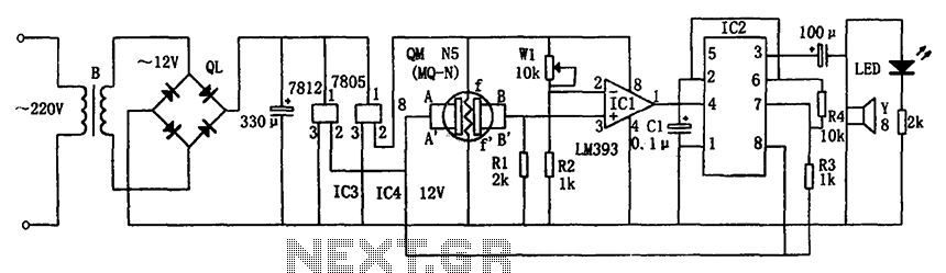
The circuit consists of a buck rectifier and voltage regulator, a gas sensor, a comparator circuit, and an alarm sound circuit. The buck regulator circuit includes a transformer, a bridge rectifier, and components such as QL, IC3 (7812), and...
Provision in the speed of a small engine DC motor speed control circuit using a small rheostat for control in the DC motor circuit diagram. The circuit for controlling the speed of a small DC motor typically incorporates a rheostat...
Thank you for your responses to my previous thread. I appreciate it. Please advise on how to convert a 24V DC and what circuit diagram should be used. To convert a 24V DC supply to a different voltage level, several...
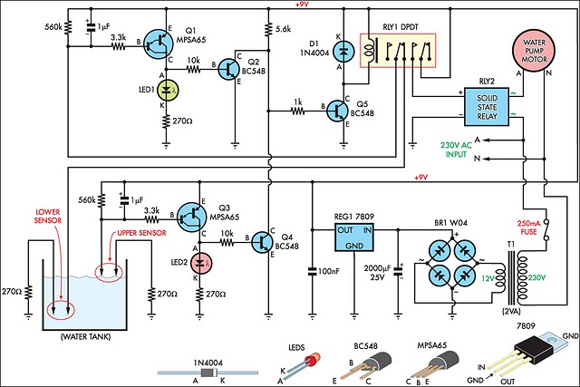
This circuit is designed to fill a header tank for a reticulated water supply on a farm. It serves eight troughs located in different paddocks, where a lack of water could have serious consequences for livestock. Previously, the tank...
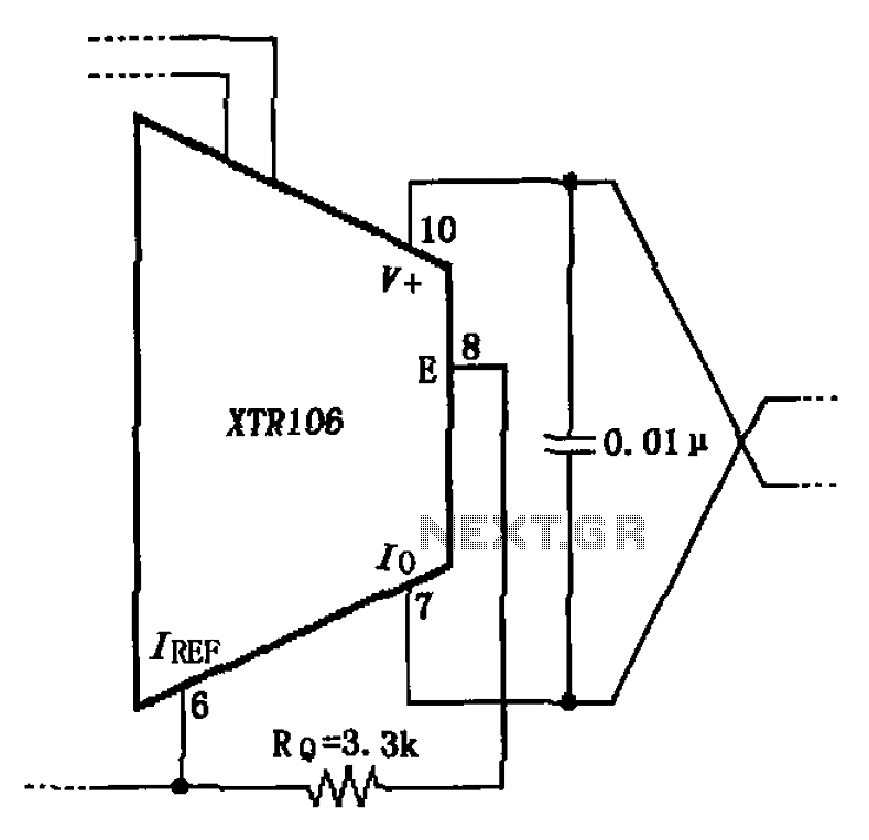
The circuit has been simplified due to the cancellation of an external transistor. The connection between the emitter terminals of the original external transistor and a 3.3k resistor will be removed, as this change has led to a decrease...