
Tube Headphone Amplifier/Preamp
To circumvent having a high voltage negative power supply for the current source (simply R4) of the differential amplifier and for improving the linearity, it is necessary to lift the cathode voltage and the grid voltage of V1 above zero volts. This is done by R7 and R8 acting as a voltage divider. This voltage divider could be built two-fold, each for one of the triodes, but since tubes have a negligible input current (gate current), the same divider gives the gate voltage for the first triode too through R6. With a gate-cathode voltage of about -1.2V and R4 = 4.7K Ohm, the plate current for each triode is about 1mA. This current increases the lifespan of the tube and gives very good results. The resistors R2 and R3 are the plate resistors and provide a plate voltage of about 170V (with a 280V power supply).
The higher the power supply voltage the higher the obtainable gain. With a power supply of 280V, the gain of the input section was measured to be about 22dB. R1 and R5 are gate resistors commonly used to reduce RF oscillations. Because the differential pair only uses one input, the other input must be grounded. C2 grounds the second input at audio frequencies. The gate is at a lifted potential for DC voltages, but is at ground for AC voltages. Like the input decoupling capacitor C1 and the interstage coupling capacitor C3, the gate capacitor C2 should be high performance too. Industrial standard MKP types (e.g. Epcos or Wima) are recommended.
The output stage is a cathode follower (gain < 1) with a triode-connected pentode EL84 instead of paralleled triodes. If triodes with high enough current (30mA or more) had been used, the plate voltage would have been about 100V-120V, resulting in a cathode resistor voltage in the range of 160V-180V. The maximum cathode heater voltage must be less than 100V, ideally below 80V, which complicates the lifting of the ground plane for the heater supply. To avoid high voltages at the output capacitor, which could pose a lethal risk, the cathode resistor voltage was limited to no more than 80V. The solution employed is the triode-connected EL84 with a 210V plate voltage and approximately 35mA current, allowing for a lower wattage and voltage across the cathode resistor. The trade-off is a higher output impedance compared to paralleled triodes, but the triode mode of the EL84 offers lower output impedance and distortion than the pentode mode.
R11 connects the second grid to the anode for the triode mode. The cathode current of 35.5mA is set with the cathode resistor R14 and the biasing resistors R12 and R13, which could alternatively be replaced with a single resistor of about 180 Ohm with a higher power rating. The output impedance of the cathode follower is approximately calculated using Rout = 1/S, where S is the transconductance of the triode-connected pentode. Based on the plate current and gate voltage graphs in triode mode, a value of S= 16mA/V is determined, yielding an output impedance of around 60 Ohms. This impedance is suitable for headphones with an impedance of 300 Ohms, ensuring an adequate damping factor. For headphones with a lower impedance of about 30 Ohms, while the gain may be reduced, satisfactory performance can still be achieved despite the lack of damping.Tube amplifiers designed for headphones have the principal property that they can be used as preamplifiers too. In most cases, the output impedance of a tube headphone amplifier is (or should be) less than the output impedance of a tube preamp.
This amplifier features relay-based input and power switching. The stepped and slow turn-on for the power supplies result in less stress for the tubes and other components and reduces turn-on thumps that could damage headphones. Most tubes fail at turn-on. Without the slow turn-on, if the tube heater filament is cold, the resistance is lower and the in-rush current of a cold filament could be very high and cause the filament to break.
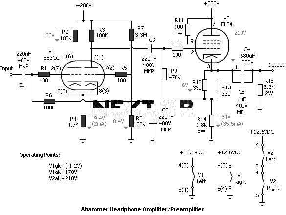
And if the filament is not hot, it is better that the plate voltage is not applied. Applying the plate voltage with cold filaments can reduce the lifetime of the tubes. Figure 1 shows the circuit of the tube amplifier designed without global feedback. It is a pure Class A OTL design with a triode-connected pentode output section. The input section was built with the double triode E83CC as a differential amplifier. The big advantage of this circuit is that the output signal can be taken from the first or from the second triode. The output at the plate of the second triode isn't phase inverting providing that the whole amplifier isn't phase inverting.
The E83CC is very often mentioned as a tube with excellent audio properties. There are selected types and different brands on the market. The E83CC is the high-grade type of the ECC83. It has a very high gain (µ = 100) and is therefore well suited for building up an amplifier with only one amplifying device. To circumvent having a high voltage negative power supply for the current source (simply R4) of the differential amplifier and for improving the linearity, it is necessary to lift the cathode voltage and the grid voltage of V1 above zero volts.
This is done by R7 and R8 acting as a voltage divider. This voltage divider could be built two-fold, each for one of the triodes, but since tubes have a negligible input current (gate current), the same divider gives the gate voltage for the first triode too through R6. With a gate-cathode voltage of about -1.2V and R4 = 4.7K Ohm, the plate current for each triode is about 1mA.
This current increases the lifespan of the tube and gives very good results. The resistors R2 and R3 are the plate resistors and provide a plate voltage of about 170V (with a 280V power supply). The higher the power supply voltage the higher the obtainable gain. With a power supply of 280V, the gain of the input section was measured to be about 22dB. R1 and R5 are gate resistors commonly used to reduce RF oscillations. Because the differential pair only uses one input, the other input must be grounded. C2 grounds the second input at audio frequencies. The gate is at a lifted potential for DC voltages, but is at ground for AC voltages. Like the input decoupling capacitor C1 and the interstage coupling capacitor C3, the gate capacitor C2 should be high performance too.
Industrial standard MKP types (e.g. Epcos or Wima) are recommended. The output stage is a cathode follower (gain < 1) with a triode-connected pentode EL84 instead of paralled triodes. If I had used triodes with high enough current (30mA or more), the plate voltage would have been, say, about 100V-120V.
Then the voltage at the cathode resistor would have been in the range of 160V-180V. As the maximum cathode heater voltage must be less than 100V or in practical terms less the 80V, the ground plane of the heater supply would have to be lifted by 80V-100V. But lifting the ground plane with all the implemented control circuits (relay control, CMOS circuit, etc.) is not good.
Furthermore, I dislike high voltages at the output capacitor. A fault of this capacitor could pose a lethal risk. Therefore I decided that the cathode resistor voltage should be not more than 80V. But what to do with the remaining 200V! There are no noval socket triodes (relatively cheap triodes) that can withstand this high plate voltage. The solution I found was the triode-connected EL84 with a 210V plate voltage and about 35mA current - permitting a cathode resistor with lower wattage and lower cathode voltage!
The drawback is the higher output impedance compared to paralleled triodes. The triode mode of the EL84 has lower output impedance and distortion compared to the pentode mode. R11 connects the second grid to the anode for the triode mode. The cathode current of 35.5mA is set with the cathode resistor R14 and the biasing resistors R12 and R13. The paralleled biasing resistors could be changed to one resistor with a value of about 180 Ohm and with a higher power handling capacity.
The output impedance of the cathode follower is approximately calculated with Rout = 1/S (S is the transconductance of the triode connected pentode). From the data sheet plate current/ gate voltage graphs in triode mode a value of S= 16mA/V, slightly higher than 12mA/V for the pentode mode is arrived and therefore Rout calculate to about 60 Ohms.
This value works fine with headphones of 300 ohms impedance concerning the damping factor. By using headphones with about 30 Ohms, not only there is no damping, but furthermore the gain of the stage would be reduced. If gain isn't that of importance low impedance headphones could give good results too, despite of the lack of damping.
🔗 External reference
Related Circuits
To omit the balance control when using separate potentiometers for the volume controls, refer to the balance control notes on the 7-tube output amplifier page. A schematic was utilized to build a modified version with separate bass and treble...
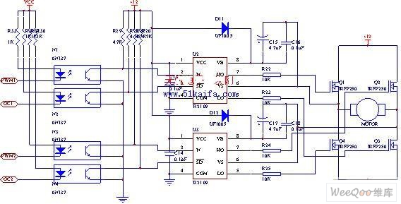
The drive circuit for the electromotor comprises a FET bridge circuit, a FET base drive circuit, a current sensor for the motor drive circuit, and a relay. The FET bridge circuit primarily consists of four high-power MOSFETs, which must...
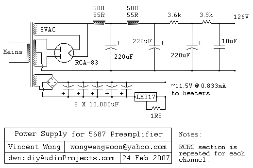
The RCA-83 rectifier utilizes 5VAC for the filament supply. The heaters for the 5687 tubes are powered by a full bridge rectifier consisting of MUR860 diodes, followed by five 10,000µF Elna capacitors. Current regulation is achieved through an LM317...
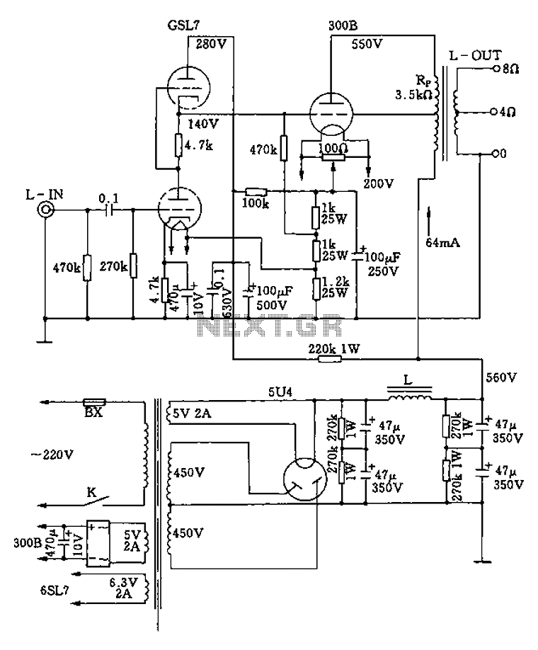
The 300B tube single-ended Class A amplifier circuit is as follows: The 300B tube single-ended Class A amplifier is a high-fidelity audio amplification circuit that utilizes a 300B vacuum tube as the primary amplification element. This design is characterized by...
.jpg)
The design data for a 3TF7 replacement is based on information from "The Ballast Tube Handbook" by Jacobi and the R-390x part list. The 3TF7 outputs approximately 12 Vac with an input voltage of around 26 Vac. The ballast...
The following diagram represents a 20W power amplifier circuit constructed using the EL34 tube component. The EL34 is a well-known tube that is highly regarded for use in power tube amplifiers. The circuit includes both the tube amplifier schematic...