
Tunnel Diode Relaxation Oscillator
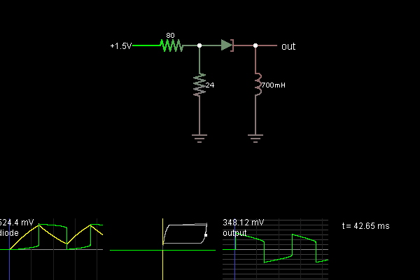
The described oscillator circuit employs a tunnel diode, which is characterized by its unique I-V (current-voltage) characteristics, specifically exhibiting negative resistance. This property is crucial for oscillation, as it allows the diode to amplify signals under certain conditions. The circuit typically consists of a tunnel diode, two resistors for biasing, and an inductor.
The two resistors are strategically placed to ensure that the tunnel diode operates within its negative resistance region. This biasing is essential for maintaining oscillation, as it establishes the initial conditions required for the diode to switch between the positive and negative resistance states.
As current flows through the inductor, the voltage across the tunnel diode increases. When this voltage reaches a certain threshold, the diode enters the negative resistance region of its curve, which is critical for the oscillation process. However, due to the inductor's positive voltage, the circuit does not allow the tunnel diode to remain in this region. Instead, the diode transitions to the right side of the curve, where the inductor's voltage becomes negative, leading to a reduction in current flow.
This current reduction causes the tunnel diode to trace the right side of its curve until it once again reaches the negative resistance region. Upon reaching this point, the diode switches back to the left side of the curve, completing the cycle. The oscillation continues as long as the circuit is powered, with the inductor and tunnel diode working in tandem to produce a stable oscillating output.
The overall design of such an oscillator circuit is compact and efficient, making it suitable for various applications, including RF (radio frequency) oscillators, signal generators, and other electronic devices requiring precise oscillation. Proper selection of component values is critical to ensure stable operation and desired frequency output.This example shows a tunnel diode used to make an oscillator. The two resistors bias the diode in its negative resistance region. As the current begins to flow through the inductor, the voltage across the tunnel diode increases until it hits the negative resistance region of its curve. The inductor still has a positive voltage across it, which req uires an increse in current, so will not allow the tunnel diode to enter the negative resistance region. Instead, it jumps over to the right side of the curve. Now the inductor has a negative voltage, so the current slows down and the tunnel diode traces out the right side of its curve until it hits the negative resistance region again, at which point the tunnel diode jumps over to the left side of the curve and the cycle begins again.
🔗 External reference
Related Circuits
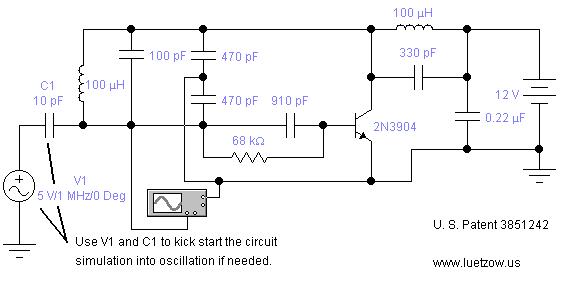
The oscillator circuits presented on this page are derived from expired or non-maintained U.S. Patents. All circuits are formatted for "Electronic Workbench 5.12" or "Multisim 7" circuit simulation software. A note regarding SPICE simulation of electronic oscillator circuits: all...
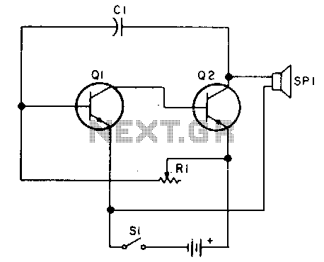
Oscillator, operates with 2 to 12 volts DC (optimal performance is achieved at 9 to 12 volts for maximum volume and clear keying). Additionally, R1 can be substituted with a 500K potentiometer, allowing the circuit to sweep across the...
Unlike conventional small-signal methods, employing large-signal, time-domain design techniques facilitates the development of low-noise grounded-base oscillators suitable for VHF/UHF applications. The implementation of large-signal, time-domain design techniques in the creation of grounded-base oscillators represents a significant advancement in the field...
This project is a piece of test equipment. It's a square wave oscillator with 6 selectable frequencies from 1Hz to 100kHz, incrementing in decade values. Its most useful application is as a Signal Injector for radios and TVs. A...
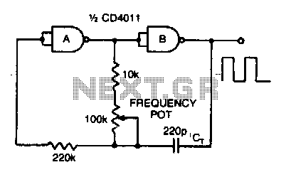
Adjusting the 100 K ohm potentiometer modifies the discharge rate of capacitor Ct, thereby affecting the output frequency. A square wave output is produced. The maximum frequency achievable with CMOS technology is constrained to 2 MHz. The circuit described involves...
A voltage-controlled oscillator (VCO) is an oscillator whose frequency is regulated by a voltage signal. The VCO discussed here can generate both triangular and square wave outputs. The control voltage can be adjusted between 5 mV and 5 V,...
Warning: include(partials/cookie-banner.php): Failed to open stream: Permission denied in /var/www/html/nextgr/view-circuit.php on line 713
Warning: include(): Failed opening 'partials/cookie-banner.php' for inclusion (include_path='.:/usr/share/php') in /var/www/html/nextgr/view-circuit.php on line 713