
Code practice oscillator II
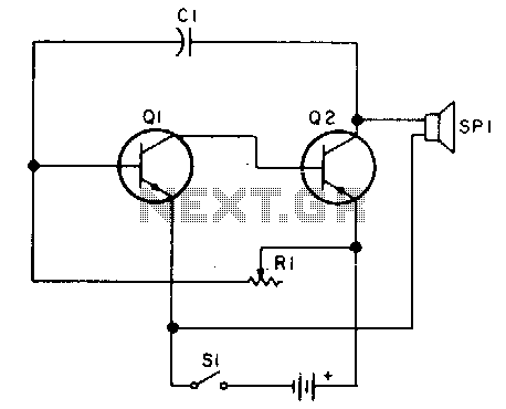
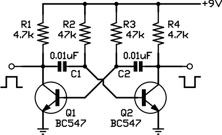
The described oscillator circuit is designed to function within a voltage range of 2 to 12 volts DC, with a specific emphasis on achieving the best audio performance between 9 to 12 volts. This voltage range is critical for ensuring that the oscillator generates a clean and robust output signal, which is essential for applications requiring high-quality audio signals and precise keying.
In this circuit, R1 plays a pivotal role in determining the frequency of oscillation. By replacing R1 with a 500K potentiometer, the user can effectively adjust the resistance, thus enabling the circuit to sweep through a wide range of audio frequencies. This feature is particularly useful in applications such as audio synthesis, where varying the frequency can produce different tones and sound effects.
The oscillator circuit typically consists of active components like operational amplifiers or transistors, which work in conjunction with passive components such as resistors and capacitors to establish the desired frequency response. The configuration may include feedback loops that stabilize the oscillation and maintain consistent output levels.
To optimize performance, it is recommended to select high-quality components that can handle the specified voltage range and provide minimal distortion. Additionally, proper layout and grounding techniques should be employed to minimize noise and enhance the overall performance of the oscillator circuit.
This oscillator design is versatile and can be applied in various electronic projects, including signal generation, sound synthesis, and modulation applications. Adjusting the frequency range via the potentiometer allows for creative exploration within the audio spectrum, making it a valuable tool for engineers and hobbyists alike.Oscillator, works with2 to 12Tdc (but 9 to 12 volts gives best volume and clean keying) R1 can be replaced with a 500K pot and the circuit will sweep the entire audio frequency. 🔗 External reference
Related Circuits
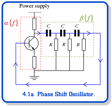
A feedback oscillator employs positive feedback to sustain oscillation. Essentially, an oscillator functions as an amplifier that incorporates feedback. A feedback oscillator is a critical component in various electronic applications, utilizing the principle of positive feedback to generate continuous waveforms....
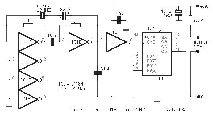
The circuit was designed to create a frequency converter using a crystal oscillator for the conversion of 10 MHz to 1 MHz. It incorporates a 7404 hex inverter. The circuit functions as a frequency divider, utilizing a crystal oscillator to...

This circuit is designed to be housed in a compact plastic or preferably metal enclosure, powered by a 9V battery. It features a level control, a male XLR connector (similar to those used in microphones), and a switch. The...
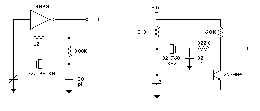
Below are a couple circuits you can use to produce a 32.768 KHz square wave from a common watch crystal. The output can be fed to a 15 stage binary counter to obtain a 1 second square wave. The...
This circuit is one of the simplest to implement but can be challenging to comprehend. It consists of a two-transistor oscillator known as an astable multivibrator, which generates a square wave output that is out of phase. Initially, it...
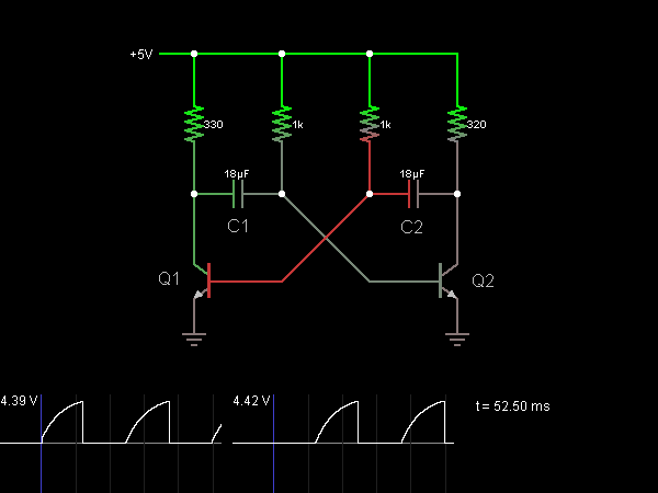
This circuit functions as an astable multivibrator, also known as an oscillator. The two transistors are interconnected in a manner that allows the circuit to alternate between two states. In one state, the base of transistor Q1 is approximately...