
Tupperware Turret Airsoft Gun Circuit

The Tupperware Turret circuit is an exemplary illustration of a compact and efficient design for remote-controlled applications. The PIC 18F4520 microcontroller serves as the central processing unit, equipped with an integrated architecture that allows for seamless interaction with peripheral devices. This microcontroller is programmed to decode the signals received from the IR receiver, which is critical for interpreting commands from the remote control.
The IR receiver is designed to detect modulated infrared signals at a frequency of 38 kHz, which is standard for most remote controls. The choice of a specialized IR receiving module enhances the circuit's performance by minimizing the need for additional components, such as separate filters and amplifiers. This integration not only simplifies the design but also improves reliability and response time.
The servo motors in the circuit are responsible for executing precise movements as dictated by the control signals from the PIC. Each servo motor is capable of rotating to specific angles, allowing for versatile positioning of the turret. The control signals sent from the PIC to the servo motors are typically in the form of pulse-width modulation (PWM), which effectively translates the desired position into a physical movement.
The firing mechanism of the airsoft gun is ingeniously controlled by the TIP120 transistor, which acts as a switch. When the microcontroller sends a signal to the transistor, it allows current to flow to the motor, activating the gear system that compresses the spring. The simplicity of using a single TIP120 transistor for this operation not only simplifies the circuit design but also ensures efficient control over the firing mechanism, making it ideal for applications requiring rapid response times.
Overall, the Tupperware Turret circuit exemplifies a minimalist approach to electronic design, effectively combining functionality with simplicity. The careful selection of components and their integration into a cohesive system demonstrates the potential for creating effective remote-controlled devices with minimal complexity.The Tupperware Turret circuit is as simple as things can get whilst still maintaining full functionality. The main parts seen in the schematic below are the: 18F4520, Servo Motors, IR Receiver and TIP120. The batteries used for this project are 4 standard AA type batteries. A 100uF capacitor is connected to power and ground to act as a DC filt er. This is a bare-bones basic power circuit, it doesn`t get any simpler. The PIC 18F4520 is the brains of this system. It takes in sensor data from the IR receiver module, which will receive commands from the TV remote control. After translating the IR commands, the PIC sends the proper signals telling the servos to move to a correlating position, or if the command to fire the airsoft gun is received, that trigger is set.
This circuit differs a little from the Infrared IR Receiver tutorial`s circuit in that a different receiving module is used that filters and amplifies the 38 KHz IR signal all in one device. This means less work for us, less space used and more functionality. The airsoft gun is little more than a motor that moves some gears to push against a spring, causing the gun to fire.
To control the firing mechanism, we must only control a motor by turning it off or on. Electrically speaking, this is a very easy thing to do and that is why only 1 high power TIP120 transistor is required to turn the motor off and on. 🔗 External reference
Related Circuits
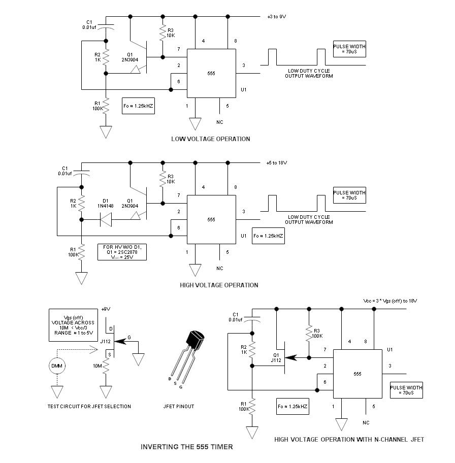
When using the 555 timer, the output polarity often appears to be incorrect, as the 555 typically cannot produce a duty cycle of less than 50%. This inverted 555 circuit is capable of generating duty cycles below 50%. The...

The AD594/595 series describes the relationship between output temperature and thermocouple voltage. For the AD594, the output voltage (Vo) is calculated using the formula: Vo = (VoJ + 16 μV) × 193.4 (mV), where VoJ represents the output voltage...

Electronic FM Telephone Transmitter Schematic. The following schematic design illustrates a circuit diagram for an FM telephone transmitter built on a compact PC board layout. This small design allows it to be easily integrated within the housing of a...

Traditional control methods for fan power equipment involve manual or relay control, which often leads to issues of poor reliability and flexibility. For instance, when the motor capacity is large, the startup process can be prolonged, resulting in high...
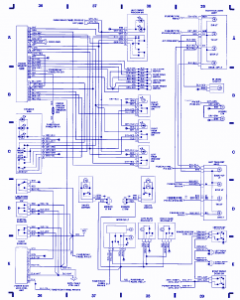
Emergency lights, fuse/relay panel, fresh air blower switch, engine control module, ignition coil, console switch, power windows, ABS control unit, ABS hydraulic unit, instrument cluster, taillight, headlight switch, automatic solenoid, ignition switch. The described circuit encompasses multiple essential components for...

The 555 timer integrates both analog and digital functions within a scaled integrated device. Typically manufactured using a bipolar process, it is designated as the 555 timer, while the CMOS version is referred to as the 7555. In addition...