
AD594 to a 597 basic application circuit
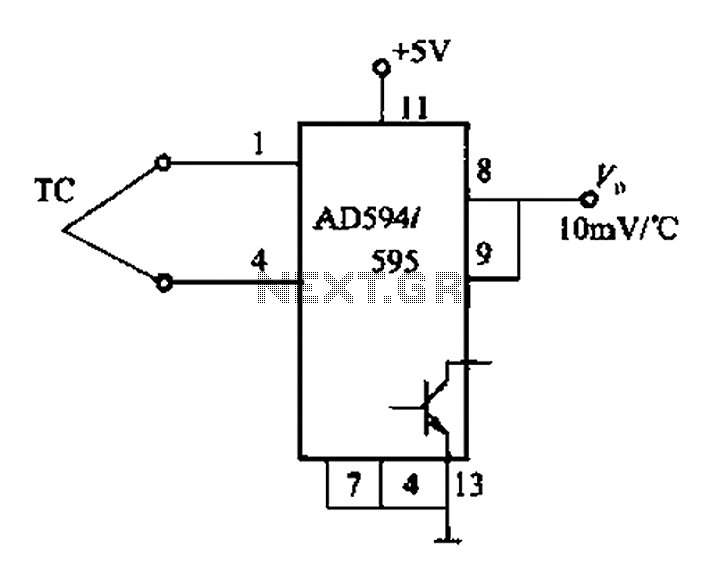
The AD594/595 and AD596/597 series are integrated circuits designed for interfacing with thermocouples, specifically J-type and K-type thermocouples. The output voltage formulas for each IC provide a linear relationship between the thermocouple voltage and the corresponding temperature, allowing for precise temperature measurements.
In practical applications, the AD594 and AD595 circuits are typically powered by a single +5V supply, which simplifies the design and reduces the number of power supply requirements. The direct connection of the thermocouple to the IC enhances measurement accuracy by minimizing potential noise and signal degradation.
The hysteresis adjustment feature is crucial in applications where temperature stability is essential, such as in control systems or alarm circuits. By incorporating resistors R1 and RPi, users can fine-tune the hysteresis effect, ensuring that the output voltage does not fluctuate unnecessarily around the set point, which could lead to false readings or alarms.
The temperature alarm indicator LED serves as a visual cue, alerting users to temperature conditions that exceed predefined thresholds. This is particularly useful in industrial settings or environments where immediate action may be required in response to temperature changes.
Overall, the AD594, AD595, AD596, and AD597 series provide robust solutions for temperature measurement and control using thermocouples, with features that enhance usability and accuracy in a variety of applications.AD594/595 and the relationship between the output temperature is: AD594: Vo (Voj + 16pLV) x193.4 (mV) Where: voJ J-type thermocouple output voltage. AD595: Vo (VOK + llIr, V) x 247.3 (mV) Where: vol (for the K-type thermocouple output voltage. AD596/597 and the relationship between the output temperature is: AD596: Vo (VoJ + 301.5yV ) x180.57 (mV) where: voJ J-type thermocouple output voltage. AD597: Vo VOK x245.46 (mV) where: VOK a K-type thermocouple output voltage. adjust the input and output pin HYS hysteresis. AD594 ~ 597 basic application circuit is shown. when the AD594/595 circuit, the thermocouple is connected directly to the lC, single + 5v power supply, can easily obtain vo rxlOmV/C (r thermoelectric the measured temperature) even the sense of output, temperature range of O ~ + 300qC; in AD596/597 basic application circuit, increasing the hysteresis regulatory elements R1- ink, RPi and temperature alarm indicator LED, RPi can adjust the output back to the voltage difference, feet for each additional 200 nA current, output will increase the temperature of 1 hysteresis output voltage vo rx lOmV gate C (r thermocouple temperature), temperature range of O-300C, accuracy is t0.020C (+25 a + lOOoC).
Related Circuits
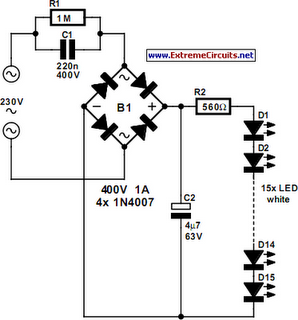
An array of white LEDs can serve as a small lamp for the living room. LED lamps are readily available, resembling standard halogen lamps, and can be installed in a standard 230-V light fixture. A capacitor is employed to...

This design circuit is for an electrostatic transducer used in ultrasonic measurement applications. It employs the LM1812 ultrasonic transceiver. The transducer (X1) and the LM1812 work together to transmit a burst of oscillations. The return echo is detected by...
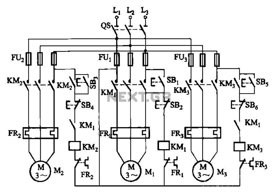
The circuit shown in Figure 3-89 illustrates a system where starting motor M1 allows motors M2 and M3 to initiate operation. Upon shutdown, motor Mz can be stopped first; however, once motor M1 is stopped (by pressing switch SB2),...
This sound-controlled lighting circuit design is utilized to adjust the brightness of connected lights in synchronization with captured sound. The sound-controlled lighting circuit operates by detecting audio signals through a microphone or sound sensor. The circuit typically consists of several...
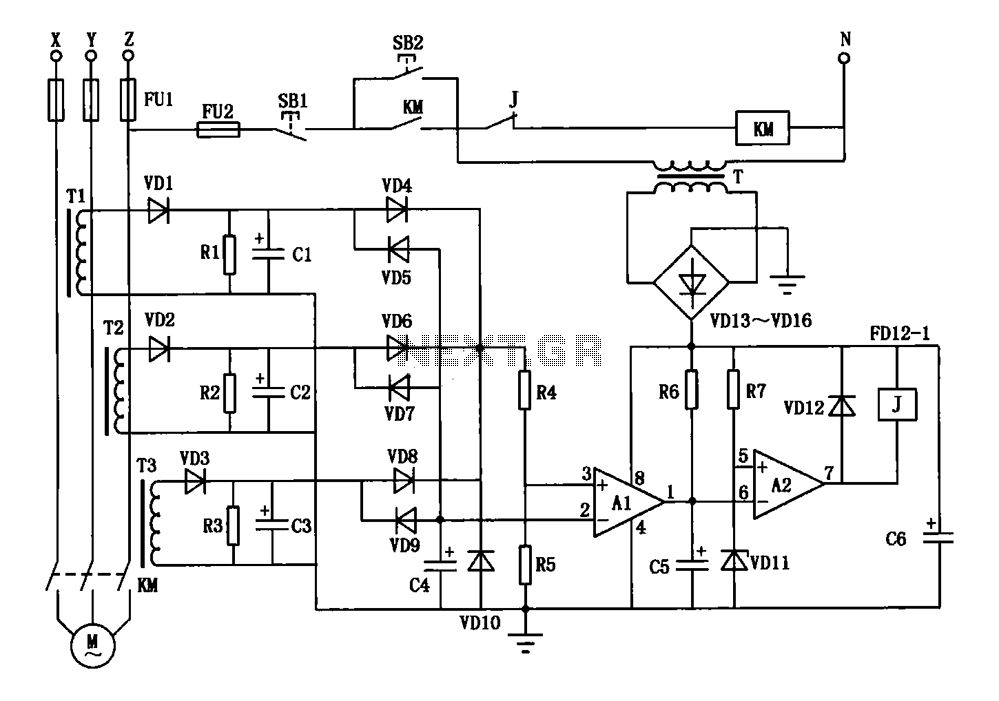
A current three-phase motor phase protection circuit is designed to detect three-phase current using homemade small current transformers T1, T2, and T3. The current signals are collected by rectifiers VD1, VD2, and VD3, while capacitors C1, C2, and C3...

This circuit is a simple telephone ringtone generator designed using minimal components. It produces a simulated telephone ringing tone and operates on a DC voltage ranging from 4.5V to 12V. This circuit can be utilized in standard intercom systems...
Warning: include(partials/cookie-banner.php): Failed to open stream: Permission denied in /var/www/html/nextgr/view-circuit.php on line 713
Warning: include(): Failed opening 'partials/cookie-banner.php' for inclusion (include_path='.:/usr/share/php') in /var/www/html/nextgr/view-circuit.php on line 713