
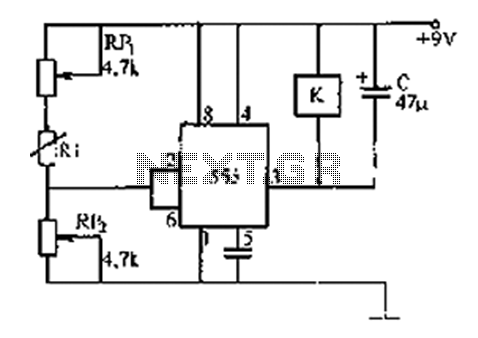
555 timer circuit temperature sensor temperature
The 555 timer is a versatile integrated circuit that serves multiple applications in timing, pulse generation, and oscillation. Its architecture consists of two voltage comparators, a flip-flop, a discharge transistor, and a resistor divider network. The device can be configured in three primary modes: astable, monostable, and bistable.
In astable mode, the 555 timer functions as an oscillator, generating a continuous square wave output. This configuration is achieved by connecting two resistors and a capacitor to the timing pins, allowing the circuit to oscillate between high and low states. The frequency and duty cycle of the output waveform can be adjusted by varying the values of the resistors and capacitor.
In monostable mode, the 555 timer acts as a one-shot pulse generator. A trigger input causes the output to transition to a high state for a specified duration, determined by an external resistor and capacitor. This mode is useful for applications requiring a single pulse output in response to an input signal.
In bistable mode, the 555 timer operates as a flip-flop, providing a stable output that can be toggled between high and low states using two separate trigger inputs. This configuration is ideal for applications such as toggle switches or memory storage.
The device's wide supply voltage range and output current capability make it suitable for driving various loads, including LEDs, small motors, and other components in electronic circuits. The 555 timer's simplicity, combined with its reliability and low cost, has made it a popular choice in both hobbyist and professional electronics projects. With minimal external components, it can be integrated into complex systems, providing essential timing and control functions across a diverse array of applications.555 timer is a combination of analog and digital functions in scale integrated devices. Usually made with bipolar process called 555, with the CMOS process is referred to 7555, in addition to single timer, there are corresponding dual timer 556/7556 Wide supply voltage range 555 timer can be 4.5V ~ 16V work, 7555 can work 3 ~ 18V, output drive current of about 200mA, so its output can be, CMOS analog circuits or compatible with TTL level in at. Low cost, reliable performance, requires only a few external resistors, capacitors, you can achieve multivibrator, Schmitt trigger, and a single-shot pulse generation and conversion circuits, etc.
Related Circuits
The component is deformed due to various thermal influences during processing, which compromises the original machining accuracy and introduces errors. In precision finishing, the effect of thermal deformation is particularly significant, leading to processing errors that can exceed 40%....
As with any audio mixer circuit, a slight loss is always introduced. The final summing amplifier has a gain of 2 or 6dB to overcome this. The input line level should be around 200mV RMS. The mic inputs are...
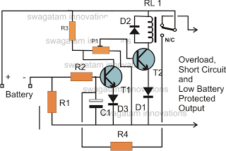
The battery voltage must pass through resistor R1 before reaching the output load. As a result, the current flowing through R1 is proportionately transformed into a voltage across it. When the battery voltage drops below a certain threshold, the...
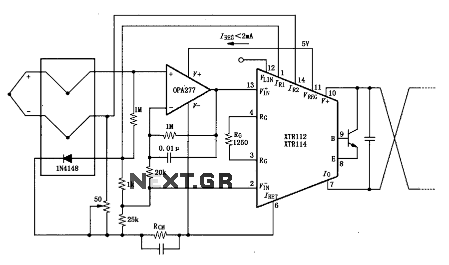
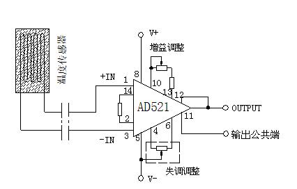
The OPA277 is configured as an inverting amplifier. This inverting amplifier utilizes high input impedance characteristics to minimize loop thermocouple offset drift. A 50-ohm potentiometer is included for calibration, allowing for the adjustment of the inverting input of the...

The schematic for the board is illustrated below. The three primary components of the board include (1) the power input and voltage regulation, (2) the L297 input and outputs, and (3) the L298 stepper motor control circuit. The motor...
This audio processor circuit features the SSM2045 integrated circuit (IC), designed specifically for electronic music applications, along with the 741 operational amplifier (op-amp) IC. The circuit is configured as a low-pass filter with a DC voltage control for gain....
Warning: include(partials/cookie-banner.php): Failed to open stream: Permission denied in /var/www/html/nextgr/view-circuit.php on line 713
Warning: include(): Failed opening 'partials/cookie-banner.php' for inclusion (include_path='.:/usr/share/php') in /var/www/html/nextgr/view-circuit.php on line 713