
Turn an old PC into a multi-channel pulse generator, for PWM/servo/stepper
PulsePar operates by leveraging the capabilities of a PC's parallel port, which traditionally serves as a means of interfacing with printers and other peripherals. The software transforms this port into an 8-channel pulse generator, enabling the user to create precise pulse signals for various applications. Each channel can be independently configured, allowing for adjustments in the period, duty cycle, and phase of the output signals. This flexibility is particularly beneficial for applications requiring Pulse Width Modulation (PWM), which is commonly used in motor control systems.
The circuit design involves connecting the parallel port pins to a series of output drivers, which can handle the necessary current and voltage levels for driving external loads. The outputs can be configured to produce square waves or pulses, effectively toggling the voltage levels between high and low states. This operation is fundamental for controlling devices such as servo motors and stepper motors, which rely on precise timing and signal characteristics for accurate movement.
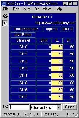
For users with older systems, the software can be run in a DOS environment, providing a straightforward interface for generating pulse signals. Additionally, the integration with the SeriCon software allows for remote control and monitoring of the pulse generation process via a serial connection to a GUI-enabled PC. This setup enhances usability, enabling users to adjust parameters and observe output in real-time.
The implementation of the PulsePar system requires careful consideration of the electrical characteristics of the connected devices to ensure compatibility and prevent damage. The output drivers must be selected based on the load requirements, and appropriate protection mechanisms, such as diodes or fuses, should be included to safeguard the parallel port and the PC from potential overcurrent conditions.
Overall, PulsePar serves as a versatile tool for engineers and hobbyists alike, facilitating the generation of complex pulse patterns for a wide range of electronic applications.PulsePar turns a PC into a multi-channel pulse generator utilizing the parallel port. The period, duty and phase of each channel are adjustable so as to be used in PWM systems as well as in testing servo and stepper (stepping) motors. If you have an old PC, boot it by dos to run PulsePar and control it by SeriCon on your GUI PC through serial port.
The free trial version of SeriCon is enough in many cases. Important features are: * PulsePar is now a 8 channel pulse generator. Pulses or square waves mean that it just turns on and off the port pins (i.e. lets the voltage levels oscillate betwee 🔗 External reference
Related Circuits
Modify a zapper circuit (similar to the Hulda Clark Zapper) to produce two different frequencies. One switch should be used to set the pulse to 15Hz, and another switch to set it to 30Hz. The nominal frequency for this...
A typical circuit for welding equipment is illustrated in the following circuit diagram. The turn-on delay can be accurately controlled with Potentiometer P2, allowing for effective discharge management. The welding equipment circuit typically incorporates several key components to ensure proper...
The heart rate measurement project utilizing fingertip photoplethysmography was constructed using salvaged components, specifically an infrared LED and a photodiode. Due to the nature of these parts, their specifications could not be provided in the article. The heart rate measurement...

The 1B32 application circuit features multiple pressure sensors as illustrated in the figure. Excitation power is supplied through the AD542, which is followed by a TIP32 transistor that drives multiple bridge sensors. The AD542 operates as a Bi-FET in...

The peak voltage sample and hold circuit is illustrated in Figure 12-50. This circuit comprises the LF398 sample and hold chip and the LM311 voltage comparator. The LF398 is responsible for outputting and inputting voltages. The LM311 compares the...
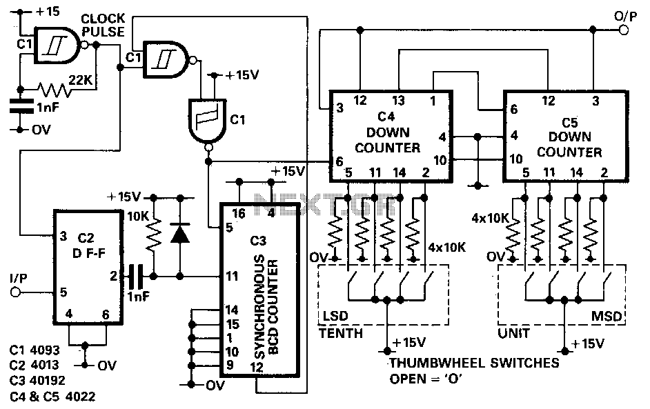
The D-type flip-flop IC2 is designed to synchronize the input signal with the clock pulse. When the clock pulse transitions from low to high and the input is high, the output of IC2 becomes high. This condition subsequently resets...