
TV audio circuit diagram TA8218AH
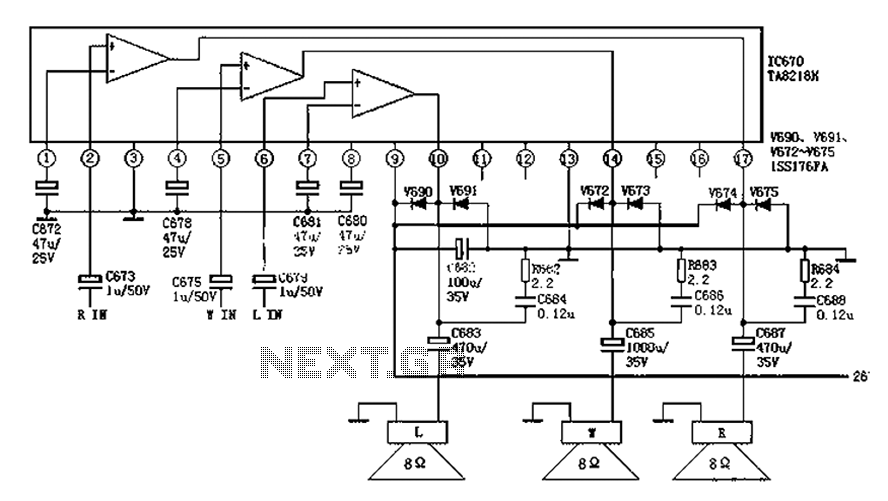
The TA8218AH is an integrated audio amplifier used primarily in color television sets, designed to enhance audio performance by providing both left and right channel outputs along with additional functionalities like bass signal processing and mute control. The pin configuration plays a crucial role in the overall operation of the circuit.
The inverting inputs on pins 1, 4, and 7 are essential for signal processing, allowing the amplifier to effectively manage audio signals from various sources. The R-channel and L-channel audio signal input terminals (pins 2 and 6) facilitate the input of audio from the television's audio source. The bass audio signal input on pin 5 is specifically tailored to enhance low-frequency sounds, contributing to an improved audio experience.
Ground connections are established through pins 3 and 13, ensuring a stable reference point for the circuit, which is necessary for proper operation and noise reduction. The power supply pin (pin 9) is critical for the amplifier's functionality, providing the necessary voltage to drive the circuit. The outputs for the left and right channels are found on pins 10 and 17, respectively, delivering the amplified audio signal to the speakers.
The mute functionality is accessible through pins 11 and 16, which can be employed to silence the audio output as needed. Additionally, the unused pins (12 and 15) may be reserved for future enhancements or specific applications, allowing flexibility in design. The filter pin (pin 8) plays a role in signal processing, ensuring that the output audio is clear and free from unwanted noise.
Overall, the TA8218AH audio circuit is a sophisticated solution for audio amplification in color televisions, with a well-defined pin layout that supports various audio processing capabilities. As shown in FIG audio circuit is commonly used in color television, TA8218AH pin functions and reference voltage: Pin 1: 1.9V-- inverting input Pin 2: 2.1V - R-channel audio si gnal input terminal Pin 3: 0V-- ground 4 feet: 1.9V-- inverting input 5 feet: 2.1V-- bass audio signal input terminal Pin 6: 2.1V - L-channel audio signal input Pin 7: 1.9V-- inverting input 8 feet: 8.9V-- filter 9-pin: 26V-- Power 10 feet: 13V - L-channel audio signal output 11 feet: 4.7V-- Mute 12 feet: 4.5V-- empty 13 feet: 0V-- ground 14 feet: 13V-- bass signal output 15 feet: 5.0V-- empty 16 feet: 4.6V-- Mute 17 feet: 13V - R-channel audio signal output
Related Circuits
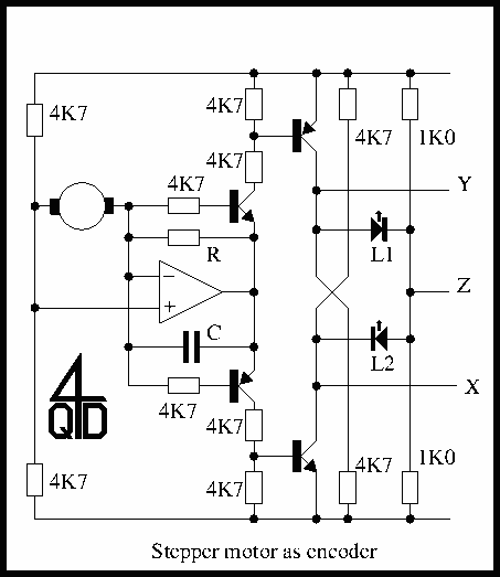
The circuit is a simple op-amp but with two diodes (the transistor b-e junctions in the feedback to split the feedback for positive and negative outputs. On positive output from the stepper coil the top transistor turns on, on...
The EUA2032 is a high-efficiency, 2.5W mono class-D audio power amplifier. A newly developed filterless PWM modulation architecture further reduces EMI and THD+N, as well as eliminates the LC output filter, thereby reducing the external component count, system cost,...
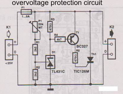
This overvoltage protection or crowbar protection circuit is used where protection against high voltage surges is necessary. The circuit consists of several components. This overvoltage protection circuit, commonly referred to as a crowbar circuit, serves as a critical safety mechanism...
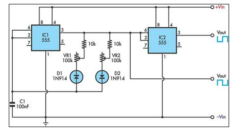
This circuit allows for the independent variation of the on/off times of a 555 timer across a wide range. This capability is not achievable with a conventional 555 timer circuit. The described circuit enhances the functionality of the standard 555...
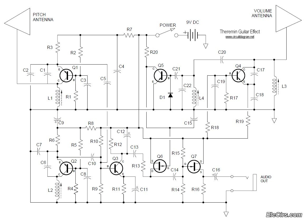
Below is the circuit diagram for the Theremin music instrument effect. A guitar or instrument amplifier is an ideal companion for the Theremin, allowing for bass or treble boost as desired, as well as fuzz (distortion) or reverberation if...
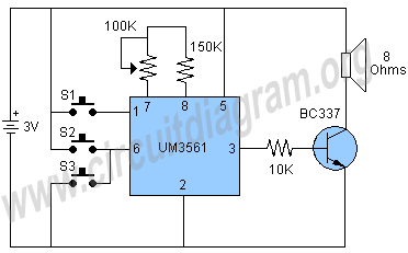
The circuit under discussion is a four-siren sound generator utilizing the UM3561 integrated circuit (IC), which is a low-power CMOS device. Four distinct sounds can be generated by activating switches S1, S2, and S3. This circuit is versatile and...