
555 Timer Circuit With Variable On/Off Times

The described circuit enhances the functionality of the standard 555 timer by enabling independent control over its timing intervals. In a typical 555 timer configuration, the timing intervals are determined by the resistors and capacitors connected to the timer, which limits the flexibility in adjusting the on and off durations. However, this circuit introduces a method to vary the on and off times separately, allowing for more complex timing applications.
To implement this, the circuit may utilize additional components such as potentiometers or variable resistors for each timing interval. The 555 timer operates in astable mode, where it continuously switches between high and low states. By connecting separate timing resistors and capacitors for the charging and discharging paths, the circuit can achieve distinct on and off durations.
The schematic would typically include the 555 timer IC, two resistors (R1 and R2), and two capacitors (C1 and C2). R1 and C1 would set the on time, while R2 and C2 would determine the off time. The values of these components can be adjusted to achieve the desired timing characteristics. Additionally, the circuit may include diodes to prevent backflow of current, ensuring stable operation during transitions.
This design is particularly useful in applications where precise timing control is required, such as in pulse width modulation (PWM) for motor control, timing circuits for LED flashing, or in generating specific frequency signals in audio applications. By allowing independent control of the timing intervals, the circuit provides enhanced versatility and adaptability for various electronic projects.This circuit enables the on/off times of a 555 timer to be independently varied over a wide range. This is not possible with a conventional 555 circuit wi.. 🔗 External reference
Related Circuits
A preamp circuit in a powered subwoofer is producing a static or popping noise, reminiscent of a scratchy or dirty sound. The preamp circuit in question is crucial for amplifying low-level audio signals before they are sent to the power...
This sound frequency meter circuit is simple to build and can be constructed in a portable format. It can measure frequencies with a minimum level of 10 mV. The sound frequency meter circuit is designed to provide an effective and...
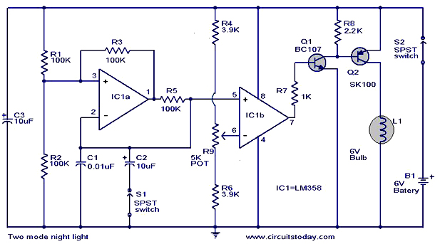
The operation and circuit diagram of a two-mode night light circuit are provided below. The two-mode night light circuit is designed to operate in two distinct lighting modes, typically offering a choice between a standard brightness setting and a dimmer,...
This is a simple 1.5V powered LED flasher circuit diagram. This circuit can flash 1.7V or 2.3V LEDs (depending on the color) using a 1.5V DC input. The LED will turn on when the 100µF capacitor is charged by...
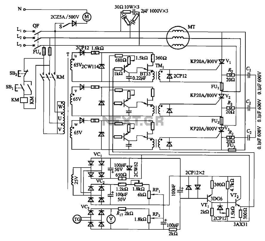
The circuit depicted in Figure 3-181 comprises three thyristors, labeled V1 to V3. The trigger circuit utilizes a single-junction transistor relaxation oscillator. The speed control circuit incorporates negative feedback. A master adjust potentiometer, designated as RPi, is used to...
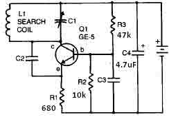
This metal detector circuit needs to be powered using a 9 volts power supply (DC) or a 9 volts battery. The C1 capacitor is a variable capacitor with a value of 365 pF, C2 is a 100 pF silver...