
TV Muter Circuit
In the circuit, when no IR signal is detected, a capacitor charges through P2 and a diode. IC1 functions as a comparator, comparing the IR voltage at its non-inverting input (pin 3) to a reference voltage applied to its inverting input (pin 2), which can be adjusted with P1 to set the switching threshold. Upon receiving an IR signal, IC2 activates T2, causing the voltage on C1 to drop rapidly below the threshold level set by P1. This transition causes T1 to switch from its 'on' state to 'off', resulting in the relay deactivating and interrupting the audio link to the stereo system for the duration of the noise interval.
For those without a stabilized 5-V supply, an alternative circuit is provided in the schematic diagram, which includes a 5-V voltage regulator that can be powered by an unregulated AC mains adapter supplying 9 V to 12 V to the 7805 (IC3). Additionally, a relay with normally-closed contacts can be used instead of normally-open contacts. In this case, the signals on pins 2 and 3 of IC1 should be swapped, allowing the relay to engage when an IR signal is detected, thus conserving power as the relay is only energized during channel switching. If the second comparator in IC1 is not utilized, it is recommended to connect pin 6 to +5 V and pin 5 to ground. To enhance noise immunity, it is advisable to shield the IR sensor from direct light exposure, particularly from fluorescent fixtures.
This circuit effectively mitigates audio disturbances caused by channel switching in tube-type televisions, ensuring a smooth and enjoyable audio experience when connected to a stereo system.Many households are still graced by tube-type television sets. If you want to connect one of these large tellies to your stereo system to improve the sound quality, this is usually not a problem because there are plenty of SCART to Cinch adapters available in accessory shops. However, with some sets your pleasure is spoiled by the fact that the au dio outputs of the SCART connector are not muted during channel switching. This can sometimes lead to nasty signal spikes, which can cause the loudspeakers of your stereo system to emit irritating popping and cracking noises. In such cases it is a good idea to fit your system with a mute circuit. Fortunately, the right time to activate the mute circuit is defined by the fact that the happy zapper presses buttons on the remote control to switch channels, and the remote control emits IR signals.
There are even inexpensive ready-made IR receiver modules available, such as the TSOP1136 used here, which produce trains of active-low pulses in response to such signals. About the circuit: when no IR signal is present, a capacitor is charged via P2 and a diode. IC1 is a comparator that compares this IR voltage (applied to its non-inverting input on pin 3) to a voltage applied to its other input on pin 2.
This reference voltage, which can be adjusted with P1, determines the switching threshold of the comparator. If IC2 receives an IR signal, T2 conducts, and as a result the voltage on C1 drops rapidly below the threshold level set by P1.
This causes T1 to change from its previous on` state to the off` state. As a result, the relay drops out and the audio link to the stereo system is interrupted for the duration of the noise interval. It`s all quite simple, as you can see. If you do not have a stabilized 5-V supply voltage available, you can use the circuit at the of the schematic diagram (with a 5-V voltage regulator) together with a simple (unstabilised) AC mains adapter that supplies a voltage in the range of 9 V to 12 V to the 7805 (IC3).
You can also use a relay with normally-closed contacts instead of normally-open contacts. In this case, simply swap the signals on pins 2 and 3 of IC1 so the relay pulls in when an IR signal is received instead of dropping out. This saves a bit of power because the relay is only energized during zapping. If you can`t find any worthwhile use for the second comparator of IC1, it`s a good idea to connect pin 6 to +5 V and pin 5 to ground.
To improve noise immunity, you should shield the IR sensor so it is not exposed directly to light from a fluorescent fixture. 🔗 External reference
Related Circuits
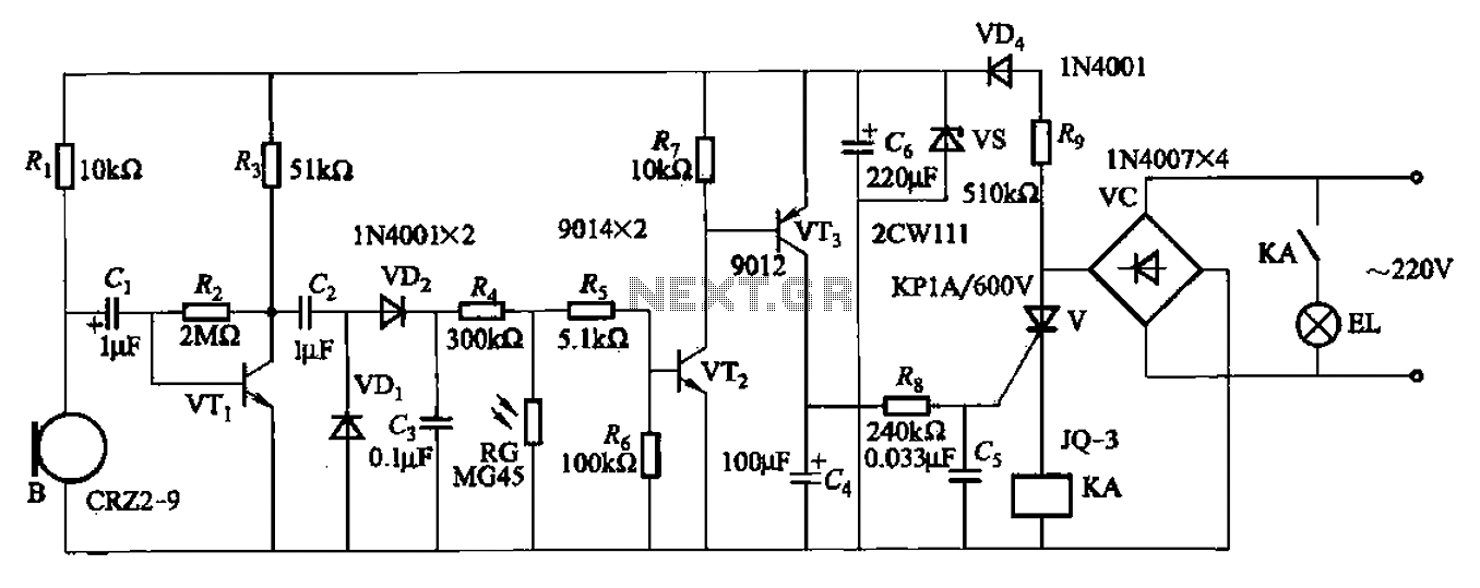
A resistor R8, capacitors Cd, and a thyristor V AC switch form a delay circuit. The lamp's lighting delay time is determined by the resistor Rs and capacitor C4, with a delay of approximately 40 seconds as indicated in...

The circuit presented utilizes NAND logic gates from the Hitachi HD series, specifically the HD74LS00, which is a quad NAND integrated circuit. A special technique has been implemented to achieve three-state operation using a single IC. Gate N1 is...
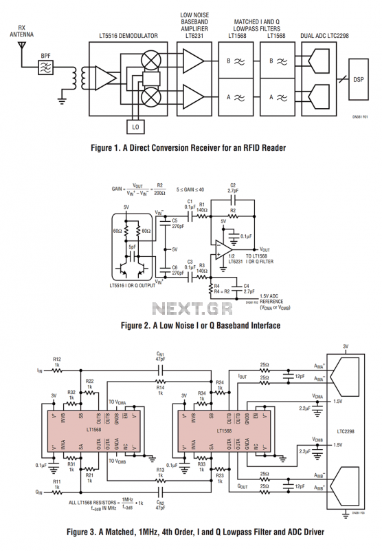
Figure 1 shows the block diagram of a direct conversion RF receiver—the receiver demodulates an RF carrier directly into a baseband signal without an intermediate frequency down-conversion (a zero IF receiver). The antenna, shared by both the transmitter and...
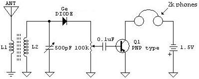
The following schematic illustrates a Crystal Radio Receiver Circuit Diagram that incorporates audio frequency (AF) amplification utilizing a Germanium transistor. The inclusion of AF amplification enhances the audio output quality. The Crystal Radio Receiver Circuit is a simple yet effective...
This UHF wideband amplifier (Ultra High Frequency amplifier) provides a total gain of 10 to 15 dB in the frequency range of 400 to 850 MHz, making it suitable for areas with weak TV signals. For optimal performance, the...
This circuit is designed to prevent further damage to old equipment that may be in unknown condition, particularly to devices that are already shorted. The circuit functions as a protective measure for vintage or malfunctioning electronic devices. It is particularly...