
Four lighting sound and light control switch circuits
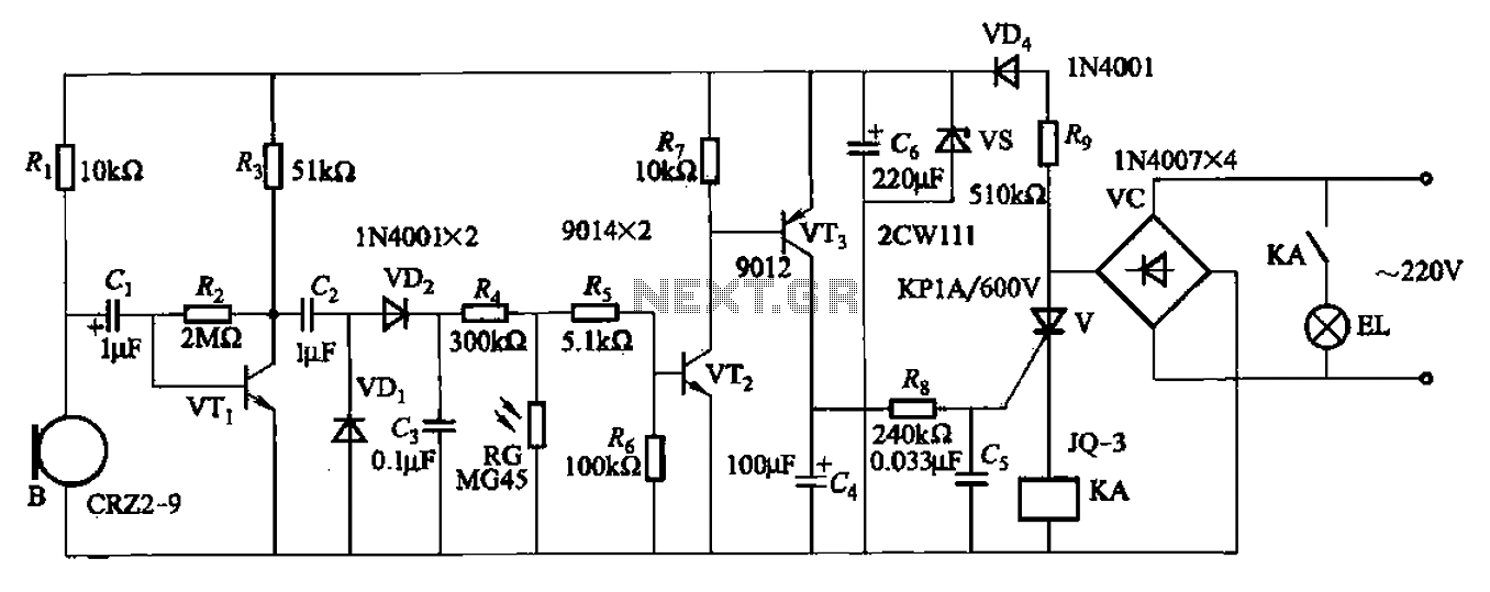
The described circuit utilizes a resistor and capacitors in conjunction with a thyristor to create a delay mechanism for lamp activation. In this configuration, resistor R8 plays a critical role in controlling the charging time of capacitor C4. As the circuit is powered, C4 begins to charge through Rs, which sets the time constant for the delay. The time constant is calculated based on the values of Rs and the capacitance of C4, which collectively dictate how long it takes for the voltage across C4 to reach the thyristor's gate trigger voltage.
Once the voltage across C4 reaches the required threshold, the thyristor conducts, allowing current to flow to the lamp and illuminating it. The delay time can be adjusted by changing the values of Rs or C4, allowing for flexibility in application. The inclusion of capacitor Cd serves as a filtering component, providing stability and reducing noise in the circuit, ensuring reliable operation of the thyristor switch.
In summary, this circuit effectively uses the principles of RC timing to create a controlled delay for lamp activation, making it suitable for applications requiring timed lighting solutions.A resistor R8, capacitors Cd and thyristor V AC switch delay composition. Lamp lighting delay time is determined by Rs, C4. Press the component parameters as shown in Figure 2- 114, the delay of approximately 40s.
Related Circuits

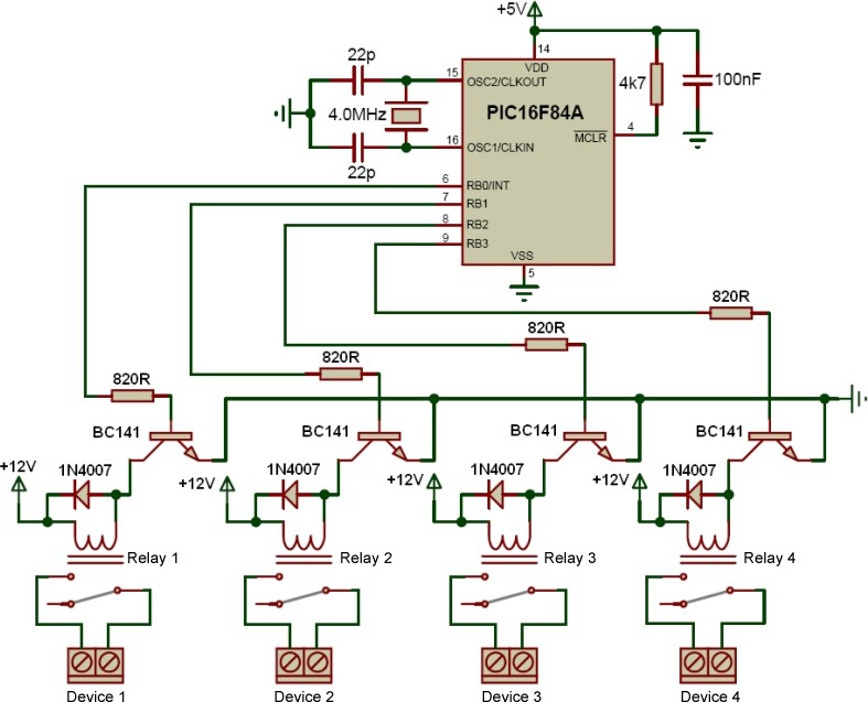
In the design of microcontroller-based electronic projects, the use of a Reset IC is critical for applications that require the microcontroller (MCU) to operate only at its optimum voltage. Without reset circuitry, the MCU may enter a tristate condition,...
The transformer is a 220V to 12V, 50Hz, and 3.6VA PCB type transformer. The model depicted is HRDiemen E3814056. Being encapsulated, it is isolated from external influences. A 250V 400mA glass fuse protects the circuit from damage caused by...
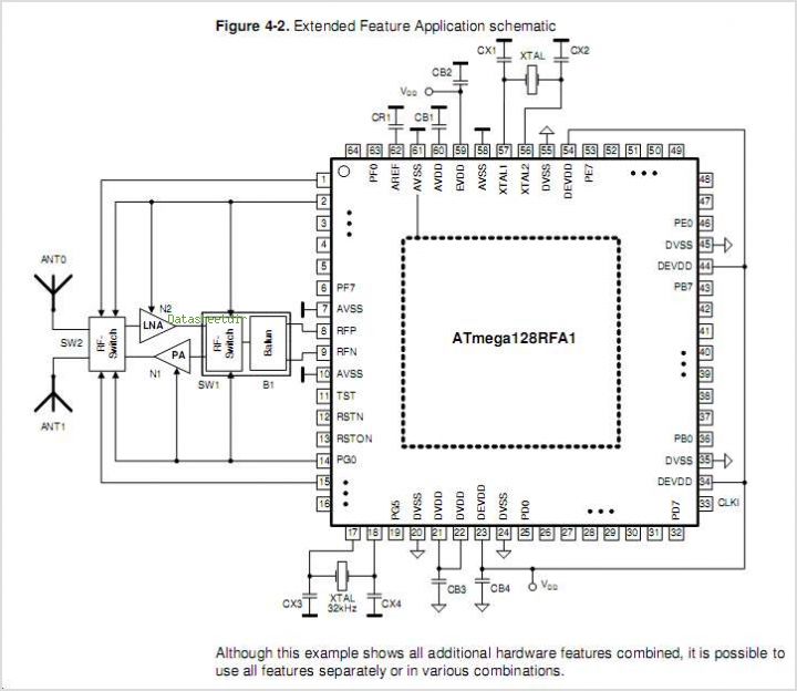
The ATR0981 is a monolithic integrated circuit (IC) produced using Atmel's advanced SiGe technology. This IC serves as a transmit and receive front-end solution, specifically designed for operation within a frequency range of 300 MHz to 500 MHz. It...
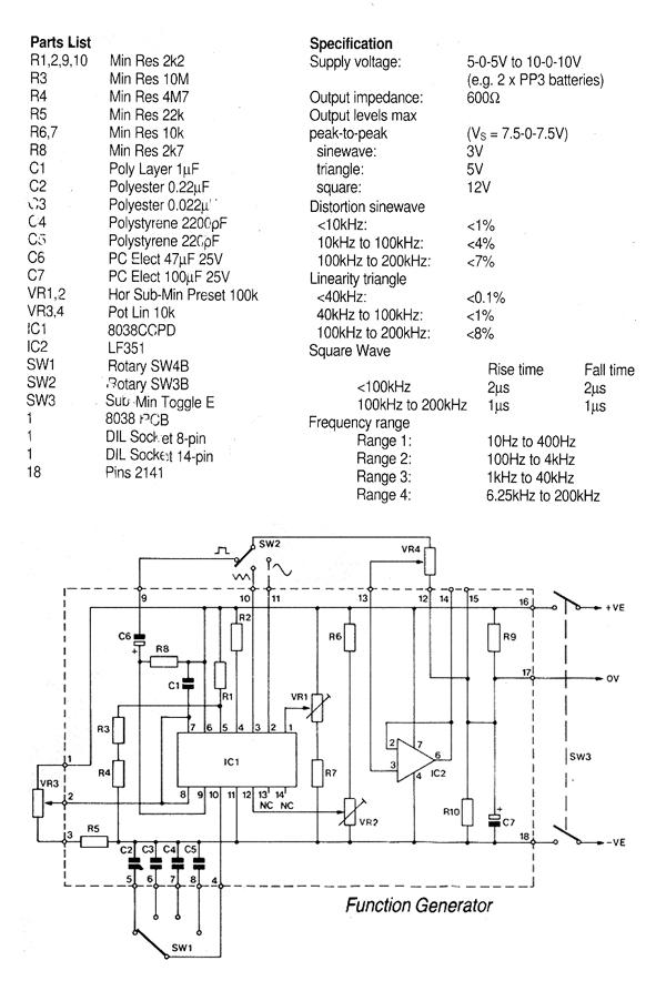
This generally results in a square wave if the frequency of oscillation is low enough relative to the amplifier's bandwidth. The schematic of a crystal-controlled oscillator features a low-frequency sine wave oscillator characterized by low distortion, wideband operation, and...
For controlling a small DC motor, such as the one found in a tape recorder, Q1 and Q2 are in saturation when both points A and B are HIGH. Component: .. To control a small DC motor effectively, a circuit...
The Saver V5.0 operates a simple clock emulation program that controls a night light, turning it on and off at preset times, specifically from 19:00 to 22:00 every day. The design is characterized by its low cost, ease of...
Warning: include(partials/cookie-banner.php): Failed to open stream: Permission denied in /var/www/html/nextgr/view-circuit.php on line 713
Warning: include(): Failed opening 'partials/cookie-banner.php' for inclusion (include_path='.:/usr/share/php') in /var/www/html/nextgr/view-circuit.php on line 713