
Twin-T RC Notch Filter
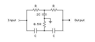
The T-notch filter is a specialized circuit designed to attenuate specific unwanted frequencies while allowing others to pass. Its operation is based on the principle of resonance, where the notch frequency is determined by the relationship between resistance (R) and capacitive reactance (Xc). In practical applications, this filter can be integrated into audio processing systems to enhance sound quality by selectively boosting bass and treble frequencies while reducing midrange interference.
In designing the circuit, the choice of component values is crucial. For instance, employing 1.5K ohm resistors in conjunction with 0.1 µF capacitors establishes a frequency response that effectively creates a -10 dB attenuation band between 500 Hz and 2 kHz. This configuration allows for precise control over the audio signal, enabling users to tailor the output to their preferences.
Furthermore, when implementing this filter in an operational amplifier configuration as a bandpass filter, careful consideration must be given to the feedback and gain settings to prevent oscillation. This may involve adjusting component values or incorporating additional resistive elements to stabilize the circuit's response.
Overall, the T-notch filter is an invaluable tool in audio engineering, providing flexibility in frequency response and enhancing the listening experience through effective frequency management.The two T-notch filter can be used to block unwanted frequencies or if placed in an op amp as a bandpass filter. the notch frequency occurs where the capacitive reactance equals the resistance (Xc = R) and if the values are close, the attenuation can be very high and the notch frequency virtually eliminated, Insertion of the filter depends on the l
oad, the output is connected to the subject so that the resistors must be of much lower value than the load for minimal loss. For audio frequencies, the filter may act as a bass and treble boost circuit by attenuating the midrange.
With 1. 5K resistors and capacitors 0. 1 uF, the band is in stop-10dB 500 Hz to 2 kHz. The depth and breadth of the reaction can be slightly adjusted to a value of 0. 5 R and adding some resistance at the C-values, If the circuit is an operational amplifier is used as a bandpass filter, the response should be reduced to avoid oscillation. Be the first of your friends to get free diy electronics projects, circuits diagrams, hacks, mods, gadgets & gizmo automatically each time we publish.
Your email address & privacy are safe with us ! 🔗 External reference
Related Circuits
What is a circuit breaker? When is an AC power line filter or a phone line filter necessary? How can a noise filter be designed? Is it possible to create a homemade surge protector? The following circuit protection options...
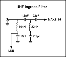
This application note discusses the design of a UHF ingress filter intended for a Satellite DBS tuner. The filter is designed to achieve 20 dB of stopband attenuation within the frequency range of 54-650 MHz, while maintaining an in-band...
A 9-12V DC power supply is connected to control point A or point B for an amateur communication receiver IF amplifier, offering two distinct options. The power frequency is set at 455 kHz with a bandwidth of 500 Hz....
The capacitor filter operates by measuring the capacitance, which is proportional to the pulse width. This measurement is compared to a nominal capacitance to determine qualification. The circuit, as illustrated in the accompanying figure, includes IC1 along with resistors...
This article describes a band-pass filter circuit diagram utilizing transistors. A band-pass filter is an essential electronic circuit that allows signals within a certain frequency range to pass while attenuating frequencies outside that range. The circuit typically consists of a...
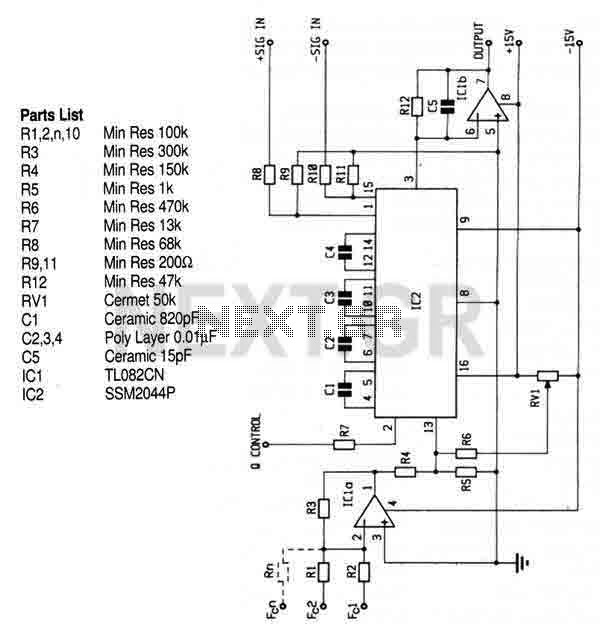
This circuit utilizes the SSM2044 integrated circuit (IC), which is a four-pole voltage-controlled filter specifically designed for electronic music applications. The on-chip voltage control of resonance facilitates straightforward interfacing with programmers and controllers. The IC is characterized by an...