
Twisted-Pair Video Cable Driver and Receiver
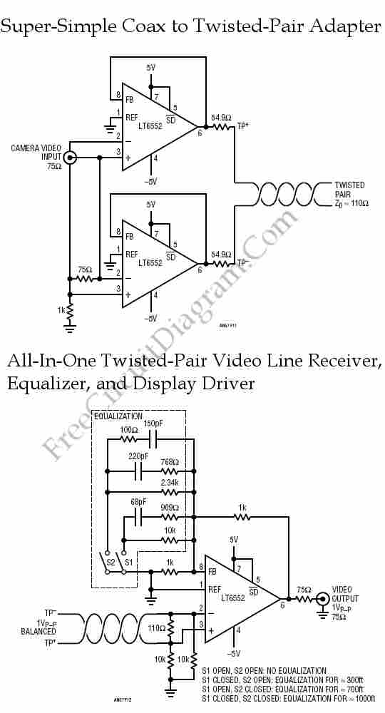
Twisted-pair wiring consists of pairs of insulated copper wires that are twisted together to form a single cable. This design helps to reduce electromagnetic interference (EMI) and crosstalk between adjacent pairs, enhancing the overall performance of data transmission. The twisting of the wires ensures that any interference affects each wire equally, allowing the differential signal to be maintained effectively.
Twisted-pair cables are categorized into two main types: unshielded twisted pair (UTP) and shielded twisted pair (STP). UTP is the most common type used in networking applications due to its cost-effectiveness and sufficient performance for most data transmission requirements. STP, on the other hand, includes additional shielding to further protect against external interference, making it suitable for environments with high levels of EMI.
The wiring technique is widely used in various applications, including local area networks (LANs), telephone systems, and other data communication systems. Categories of twisted-pair cables, such as Cat 5e, Cat 6, and Cat 6a, define the performance specifications, including bandwidth and data rate capabilities, with each successive category providing improved performance.
In summary, twisted-pair wiring is a fundamental technology in modern data communication, offering a reliable and efficient means of transmitting data over short to moderate distances within buildings. Its design and categorization allow for flexibility in application and performance, making it a preferred choice in many networking scenarios.Twisted-pair wiring is a wiring technique that usually used for in-building data communication. Compared to conventional coaxial-cable, this technique offers. 🔗 External reference
Related Circuits
The electronic diagram of the monophonic FM receiver made with TDA7088T is shown on Pic.4.12. If built with SMD components it can be placed in a matchbox, altogether with two button-type batteries. The operating principle of this device is...
The BTS412B functions as two high-side power MOSFET switches, while the BU271L components rated for 50V serve as the low-side switches. Together, these elements can form a bi-directional H-bridge DC motor drive circuit, as depicted in Figure 11-1l. This...
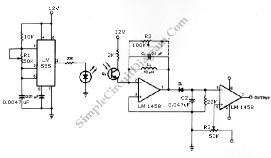
The infrared transmitter and receiver circuit depicted in the schematic diagram can function as a remote control. The transmitter operates as an oscillator circuit, with the frequency adjustable via the R1 potentiometer (or trimmer pot). This oscillation ensures that...
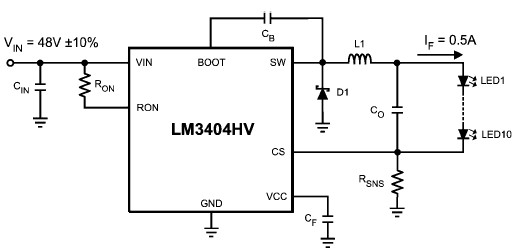
The LM3404 is a monolithic switching regulator that can be utilized to design a simple constant current driver for high-power LEDs. This LED driver project is suitable for automotive, industrial, and general lighting applications. Hysteretic control of the on-time,...
XTAL1 drives amplifier Q3/Q4, which is tuned to 2.25 MHz. The detected signal is fed to audio amplifier IC1. A 9-V supply is used. The circuit operates at 2.25 MHz and is designed to be used with an ultrasonic...
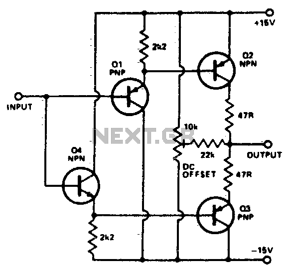
To buffer a test generator to the outside world requires an amplifier with sufficient bandwidth and power handling capability. The circuit is a very simple unity gain buffer. It has a fairly high input impedance, a 50-ohm output impedance,...
Warning: include(partials/cookie-banner.php): Failed to open stream: Permission denied in /var/www/html/nextgr/view-circuit.php on line 713
Warning: include(): Failed opening 'partials/cookie-banner.php' for inclusion (include_path='.:/usr/share/php') in /var/www/html/nextgr/view-circuit.php on line 713