
Two-component metal detector
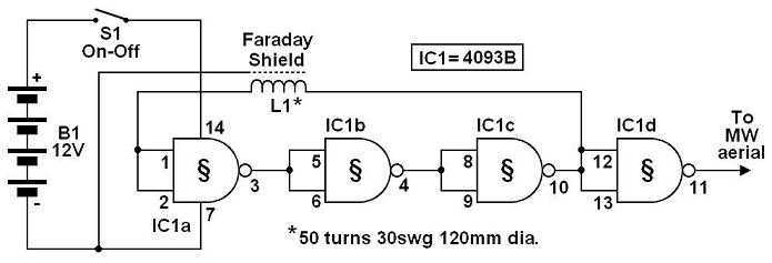
The described circuit is a basic metal detector utilizing the 4093 quad Schmitt NAND IC, which is known for its ability to provide clean switching signals and is suitable for low-frequency applications such as metal detection. The circuit operates on a simple principle where the search coil acts as an inductor, generating a signal in response to the presence of metallic objects.
The 4093 IC consists of four independent NAND gates, but only one gate is utilized in this configuration. The output from one of the gates (IC1d) is connected to a medium wave (MW) radio aerial, which serves as a receiver for the electromagnetic signals induced by the search coil. The connection to the radio is crucial, as it allows the detection of the frequency changes caused by nearby metallic objects.
The search coil is typically constructed by winding a specific number of turns of insulated wire around a non-conductive form. The inductance of the coil is a critical parameter, as it determines the sensitivity of the metal detector. The circuit is powered by batteries, and a switch is included to turn the device on and off, conserving battery life when not in use.
For optimal performance, if the radio is equipped with a Beat Frequency Oscillator (BFO) switch, it should be activated. The BFO switch allows the radio to detect frequency variations, enhancing the ability to identify the presence of metal. When a metallic object is detected, the inductance of the search coil changes, resulting in a shift in the frequency detected by the radio, which can be heard as a change in tone or volume.
This simple yet effective design exemplifies the fundamental principles of metal detection technology, making it an excellent project for electronics enthusiasts and beginners in the field.The circuit shown must represent the limits of simplicity for a metal detector. It uses a single 4093 quad Schmitt NAND IC and a search coil -- and of course a switch and batteries. A lead from IC1d pin 11 needs to be attached to a MW radio aerial, or should be wrapped around the radio.
If the radio has a BFO switch, switch this ON. 🔗 External reference
Related Circuits
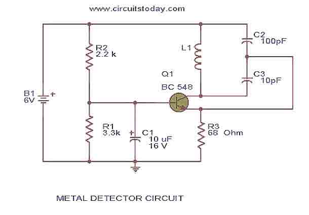
This is the circuit diagram of a low cost metal detector using a single transistor circuit and an old pocket radio. This is nothing but a Colpitts oscillator working in the medium band frequency and a radio tuned to...
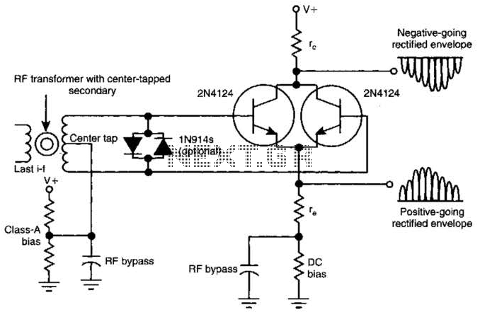
This amplifying full-wave detector circuit is simple yet sensitive, featuring an almost zero rectification threshold. It provides a highly linear RF load to the final IF stage. The gain for the collector output is approximately given by r jre,...

The circuit can be used to determine whether an input signal falls within a specific frequency range. The device comprises three integrated circuits (ICs), including a dual monostable multivibrator and two dual D-type flip-flops. The signal whose frequency is...
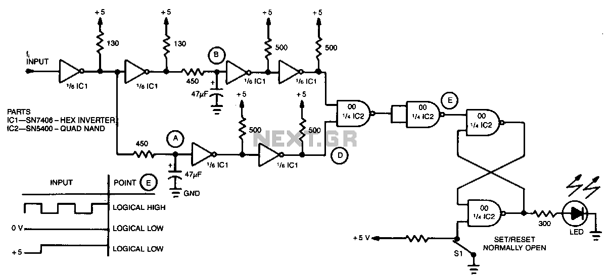
A simple inverter and NAND gate can be connected to create a highly compact and reliable digital frequency detector. This circuit is capable of detecting frequencies up to 3 MHz with a 50% duty cycle. When a frequency appears...
This circuit is designed to indicate when room noise exceeds a predetermined threshold, utilizing a flashing LED to signal this condition. Three fixed noise levels are selectable: 50 dB, 70 dB, and 85 dB. The circuit employs two operational...
This circuit employs a synchronous demodulator to separate a 1 KHz signal from noise and measures the amplitude of the 1 kHz signals once a second at about 60 microvolts per count then sends the measurements via an RS-232...