
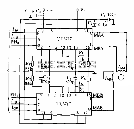
Two-phase stepper motor drive system circuit
The two-phase stepper motor control system utilizing the UC3717A is designed to provide precise positioning and speed control for applications requiring accurate motion. The UC3717A is a versatile integrated circuit that facilitates the generation of control signals necessary for the operation of stepper motors. By employing two of these ICs, the system can effectively manage the stepper motor's phases, allowing for smooth and reliable operation.
The microcomputer interface can be programmed to execute various control algorithms, which can be tailored to the specific requirements of the application. This flexibility enables the implementation of different operational modes, such as full-step, half-step, or microstepping, enhancing the motor's performance and resolution.
CMOS digital circuits are employed to generate the control signals, ensuring low power consumption and high-speed operation. The design can incorporate additional features such as speed control, direction control, and acceleration profiles, which can be programmed into the microcomputer. This adaptability makes the system suitable for a wide range of applications, from robotics to CNC machinery.
In summary, the combination of UC3717A components and microcomputer control provides an effective solution for managing two-phase stepper motors, allowing for precise control and versatility in various operational modes.Two-phase stepper motor typical application is shown in Figure 5-15 Xin, made up of two pieces UC3717A can form a two-phase permanent magnet or hybrid stepping motor microcomputer control system. By the microcomputer software design or by the TTI. , CMOS digital circuits can generate the correct hardware I ,, 1. , PHASE two-phase control signal, operation of several control modes.
Related Circuits
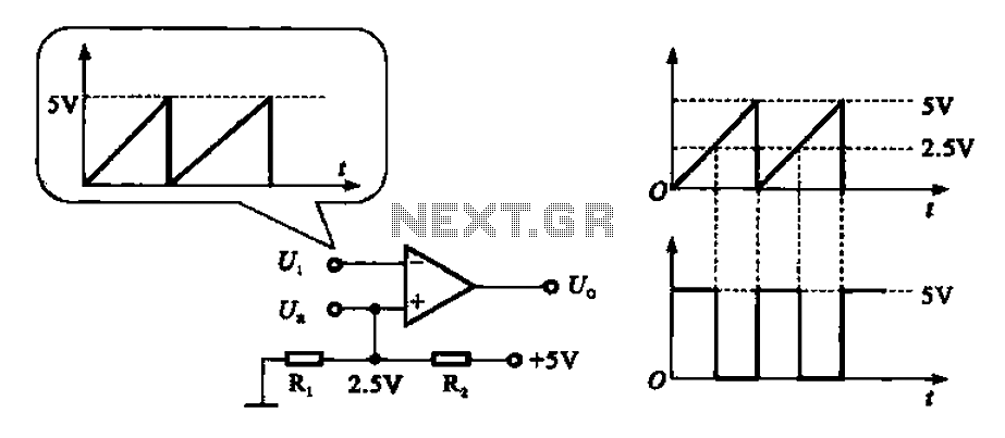
The addition and subtraction functions of an operational amplifier are facilitated through an external feedback network, which places the integrated operational amplifier in a deep state of negative feedback. In this linear region, the relationship between input and output...
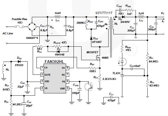
A simple 5-volt switching power supply electronic circuit project can be designed using the FAN302HL, a highly integrated PWM controller integrated circuit. This IC provides several features that enhance the performance of general flyback converters. The constant-current control of...
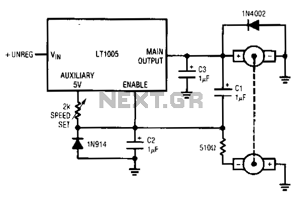
This circuit utilizes a tachometer to generate a feedback signal that is compared to a reference provided by the auxiliary output. Upon power application, the tachometer output is initially zero, allowing the regulator output to activate and supply current...
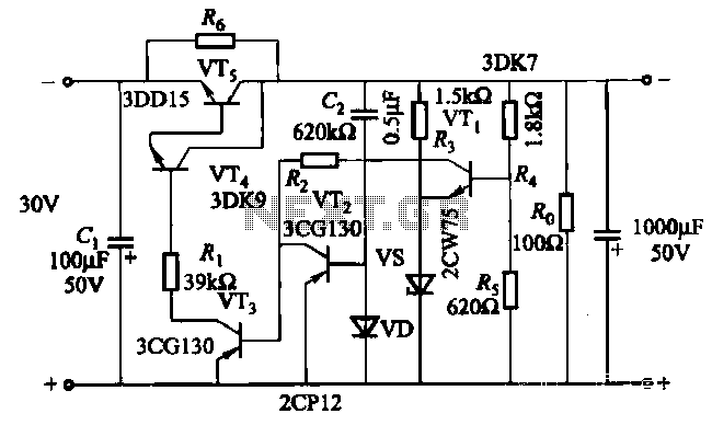
The soft start circuit refers to a power circuit where the output voltage gradually increases to a specified value, thereby protecting the load circuit from unwanted voltage surges. It can output a voltage of 24V and a current of...
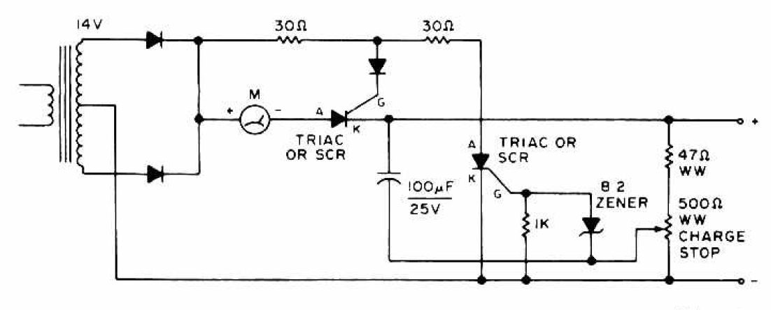
The charging circuit features adjustable voltage output settings, allowing for regulation of the charging voltage supplied to the battery. The use of a potentiometer facilitates precise voltage management, with adjustments possible down to the millivolt range. Refer to the...
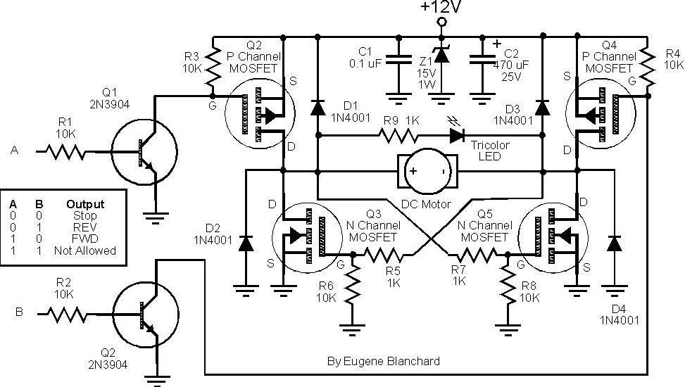
At 9 volts, the maximum stalled current of the motor types intended for use will be 700 mA. The selection of appropriate MOSFETs is crucial, particularly regarding their ratings for current and voltage handling. However, there are concerns about...