
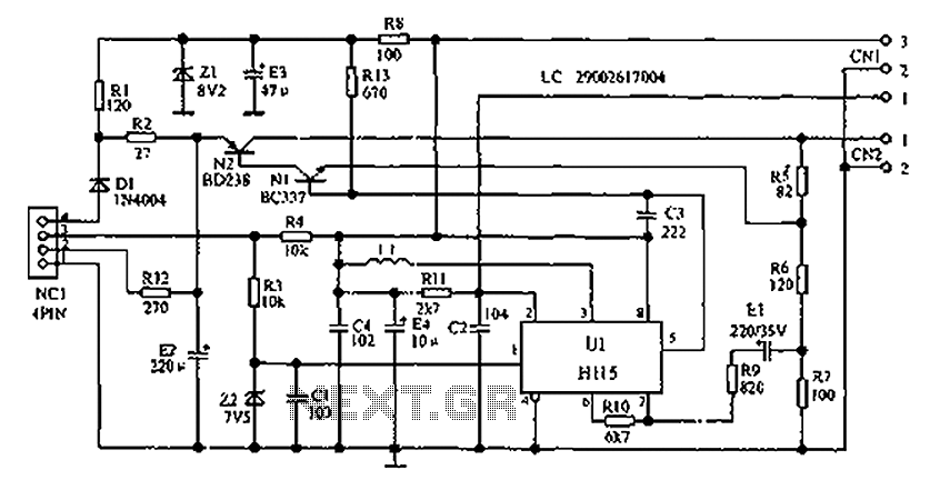
Charger circuit equipped with a regulator circuit output voltage Schematic Diagram
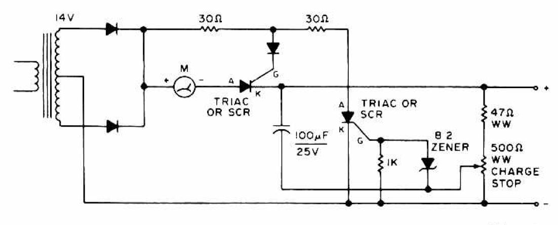
The circuit design incorporates a voltage regulator that ensures a stable output voltage suitable for charging various battery types. The potentiometer is connected in a voltage divider configuration, enabling fine-tuning of the output voltage. This flexibility is crucial for different battery chemistries, which may require specific charging voltages to optimize performance and longevity.
The input section of the circuit typically includes a transformer or an AC to DC converter to provide the necessary input voltage. Following this, a rectifier circuit converts the AC voltage to a pulsating DC voltage, which is then smoothed using capacitors to reduce ripple. The voltage regulator, often implemented using integrated circuits such as the LM317 or similar, maintains a constant output voltage despite variations in input voltage or load conditions.
Additionally, the circuit may include protection features such as fuses or diodes to prevent overcurrent situations and reverse polarity connections. An LED indicator can also be incorporated to show the charging status, providing visual feedback to the user.
Overall, this adjustable voltage charger circuit is designed for efficiency and reliability, ensuring safe and effective charging of batteries across a range of applications.The circuit charger is equipped with voltage output settings, so that we can regulate how much voltage to charge the battery. And the settings using the potentio making it easier for us managing voltage up to a mV. See charger circuit below : You are reading the Circuits of Charger circuit equipped with a regulator circuit output voltage And this
circuit permalink url it is 🔗 External reference
Related Circuits
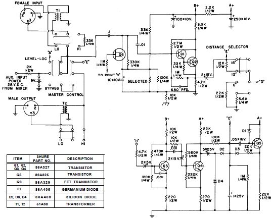
SHURE is an American corporation that manufactures consumer and professional audio electronics, including microphones, phonograph cartridges, and discussion systems. SHURE Incorporated is a well-established entity in the audio electronics industry, recognized for its innovative design and high-quality products. The company...
Lithium Ion batteries pack a lot of power by weight compared to other types. There are 2 things that need to be handled differently than nicad or NiMH. They cannot be used as a direct substitute (even if they...
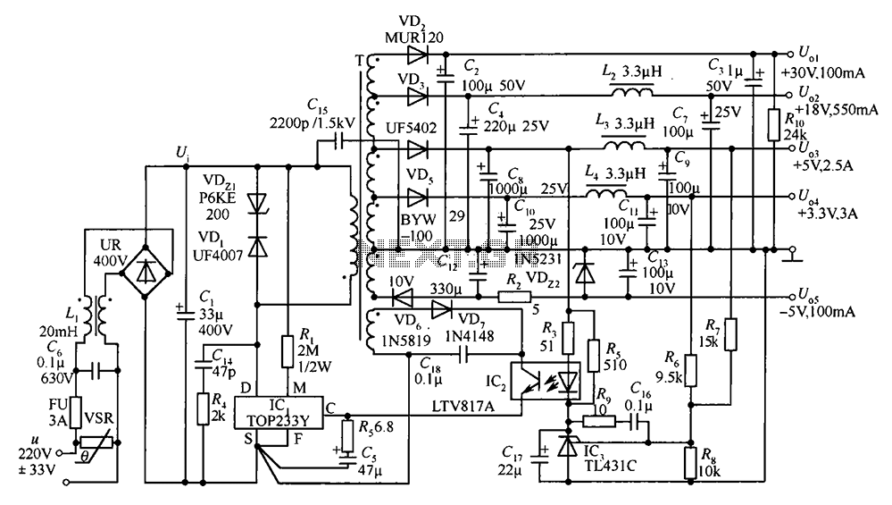
A 35W switching power supply circuit designed for a set-top box output is depicted in Figure 5. It features five distinct voltage outputs: Uo1 (+30V, 100mA), Uo2 (+18V, 550mA), Uo3 (+5V, 2.5A), Uo4 (+3.3V, 3A), and Uo5 (-5V, 100mA)....
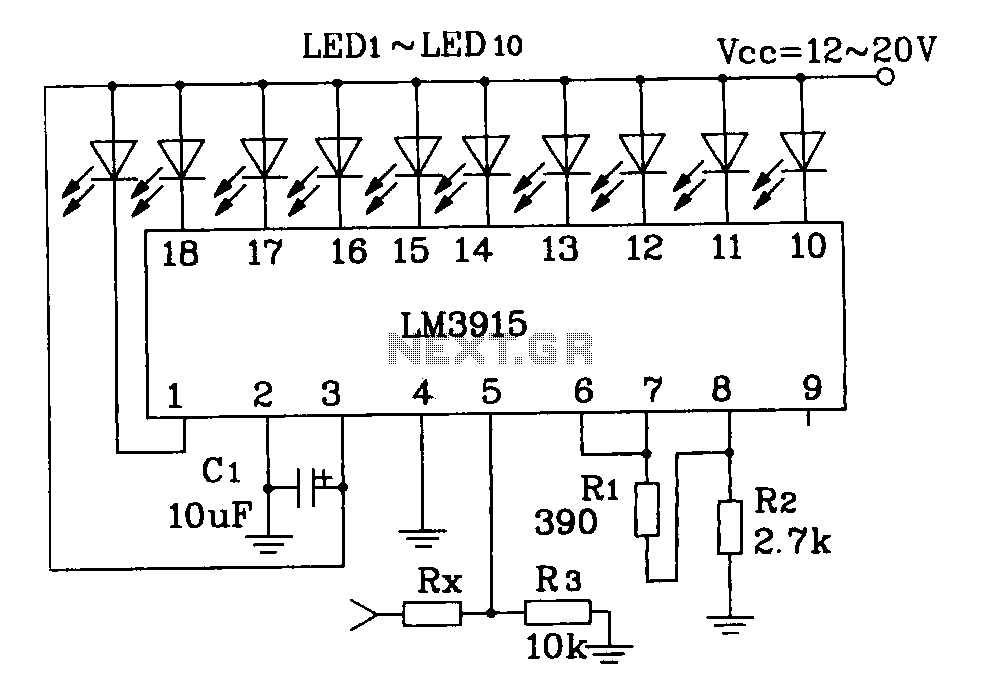
This document describes a simple LM3915 audio power meter circuit diagram. It notes that if the internal resistance of the speaker is 4 ohms, a resistor value of 10k ohms should be used for Rx. For an 8-ohm speaker,...
The following describes the circuits of a minibus odometer, which integrates electronic and mechanical components to form a new type of instrument for measuring distance and speed. Pulse signals are generated by the locomotive speed detection system and transmitted...
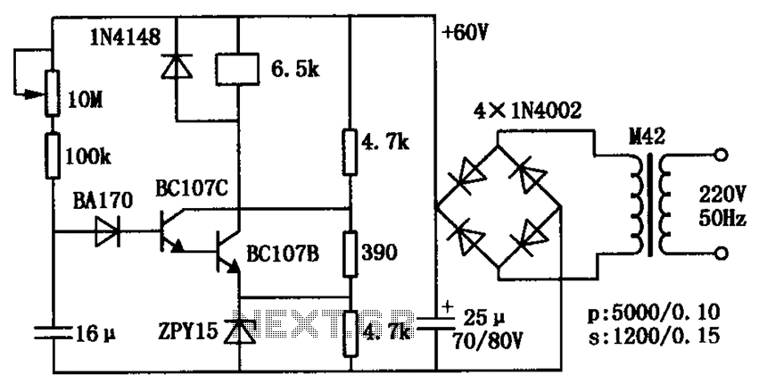
The circuit consists of a transistor relay delay pull mechanism. Initially, with a 16 µF capacitor at zero voltage, both transistors are off, and the relay remains inactive. As the 16 µF capacitor charges over time, the voltage increases...