
Simple Metronome With Transistors

The astable multivibrator configuration of a flip-flop consists of two transistors arranged in a feedback loop, allowing it to oscillate continuously between its high and low states. The output frequency of this circuit can be determined by the values of the timing components, which typically include resistors and capacitors connected to the transistors.
In this specific application, the 100k resistor plays a critical role in setting the biasing point of the transistors, effectively controlling the charging and discharging time of the timing capacitor. By modifying this resistor, the oscillation frequency can be adjusted, which is essential for tuning the metronome to the desired beats per minute (BPM).
The circuit can be designed with additional components such as diodes to protect against reverse polarity and capacitors to filter out noise, ensuring stable operation. The output signal can drive an LED or a speaker, providing visual or auditory feedback, respectively. The design also allows for further customization by incorporating variable resistors or capacitors, enabling the user to fine-tune the timing signal according to specific requirements.
Overall, the astable multivibrator circuit using a flip-flop is a versatile solution for generating periodic timing signals, making it suitable for various applications in music and timing devices.Flip-flop, as an astable multivibrator, can be used to generate timing signal in music: metronome. By adjusting transistor bias resistor using a 100k.. 🔗 External reference
Related Circuits
Construct a basic audio amplifier utilizing transistors. While integrated circuit (IC) designs are available for this purpose, the intention is to use transistors to gain practical knowledge about their amplification capabilities. The article "Amplifier Basics - How Amps Work...

The following circuit illustrates a simple TV transmitter circuit diagram. This circuit is based on the LM1889 integrated circuit (IC). Features include quadrature chroma modulators and RF capabilities. The circuit utilizes the LM1889 IC, which is designed for television applications,...
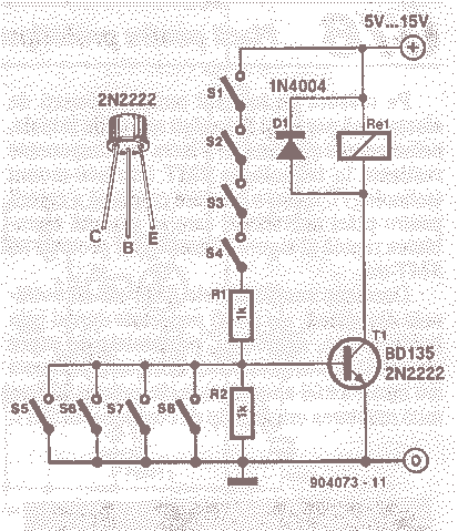
To put the relay in tension the 4 buttons S1 S4 must be pressed. If anyone of the 4 buttons S5 S8 are pushed the relay doesn't tension (doesn't receive supply voltage). The supply voltage must be equal to...

This DC-to-AC inverter utilizes the well-known 555 timer IC. A 555 oscillator circuit drives a buffer amplifier composed of transistors Q1, Q2, and Q3. The circuit operates at a frequency range of 150 to 160 Hz. Transformer T1 can...
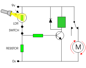
The following circuit illustrates a simple light sensor circuit diagram. Features include crocodile technology for simulating circuit operation, and an LDR (Light Dependent Resistor) is utilized. The simple light sensor circuit operates on the principle of light intensity detection using...

For the regulation needs a transmitter or generator in mpa'nta the CB, that is to say in the region 27MHz. If you have a certain friend with CB, you convince you to help. Connect a piece of cable around...