
Two-tone electronic doorbell 1
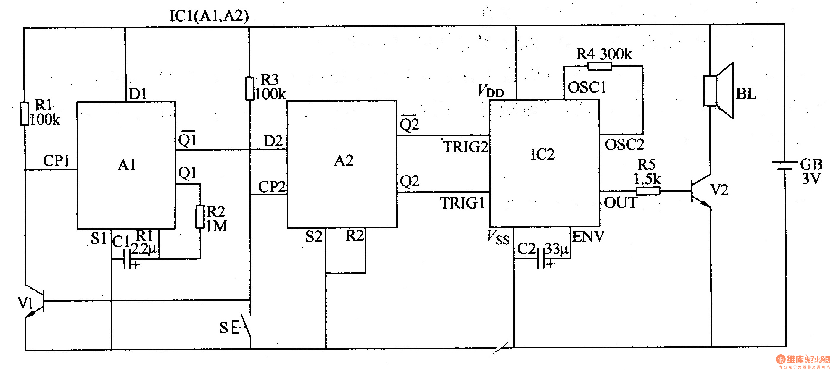
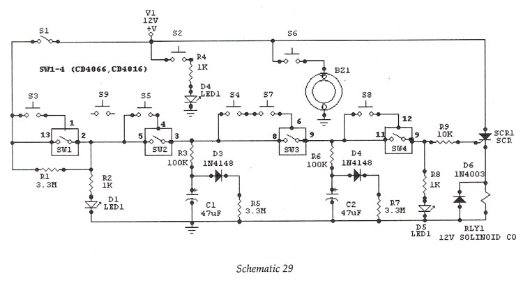
The two-tone electronic doorbell circuit operates by utilizing a combination of analog and digital components to produce distinct audio signals in response to the activation of the doorbell button. When the button (S) is pressed, it triggers the input circuit, which initiates the operation of the transistor (V1). This transistor acts as a switch, allowing current to flow through the resistors (R1-R3) and charging the capacitor (C1).
The dual D flip-flop integrated circuit (IC1) plays a crucial role in generating the two-tone sound. It is configured to alternate between two different output states, each corresponding to a specific audio tone. The outputs A1 and A2 are connected to the audio output circuit, which typically includes an amplifier and a speaker. The audio output circuit is responsible for converting the digital signals from the flip-flop into audible sounds.
The design of the circuit ensures that the two tones produced are distinct and recognizable, enhancing the functionality of the doorbell. The choice of components, such as the specific values of the resistors and capacitor, as well as the characteristics of the transistor, can be adjusted to fine-tune the sound output and response time of the doorbell. Overall, this circuit provides a reliable and efficient solution for a two-tone electronic doorbell system.The two-tone electronic doorbell circuit is composed of the input trigger circuit and audio output circuit, ans it is shown in Figure 3-107. The input trigger circuit is composed of the doorbell button S, transistor V1, resistors Rl-R3, capacitor Cl and dual D flip-flop integrated circuit ICl (Al, A2).
Audio output circuit consists of the audio output circui.. 🔗 External reference
Related Circuits
Although it may lack the aesthetic appeal of traditional mercury barometers, which feature long glass tubes mounted on intricately carved and polished wood, the Torricelli barometer being discussed serves as a functional equivalent and electronic replica of the classic...
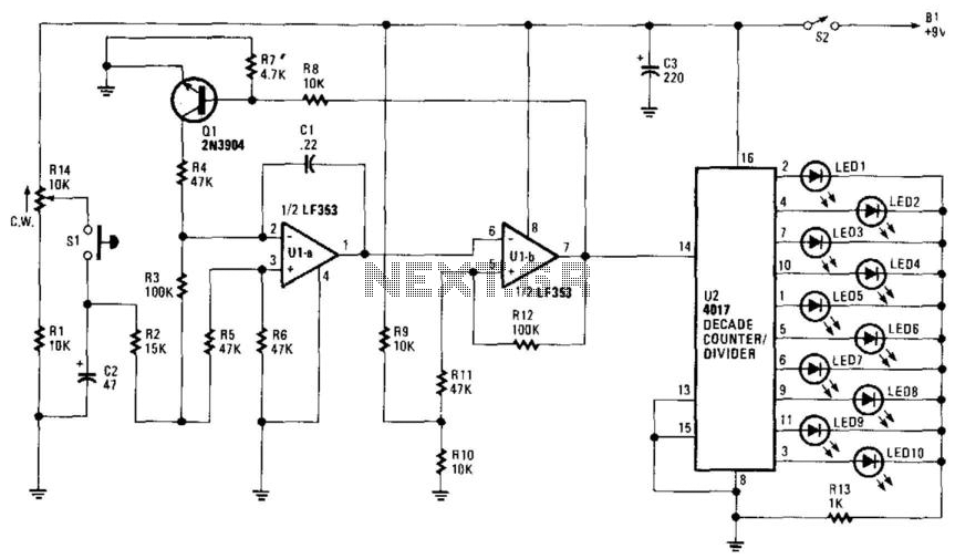
R14 is configured to establish an initial "starting" speed for the oscillators U1A and U1B. As capacitor C2 charges, the oscillation gradually slows down during the discharging phase of C2, creating a roulette-wheel effect on LED S1 through resistor...
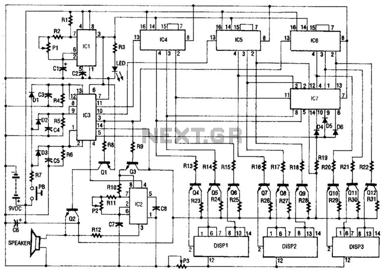
The slot machine's realistic action is provided by seven integrated circuits (ICs) and three displays. Two 555 CMOS timer ICs generate pulses. IC1 generates the clock pulses for the entire electronic slot machine. The pulses are coupled from the...
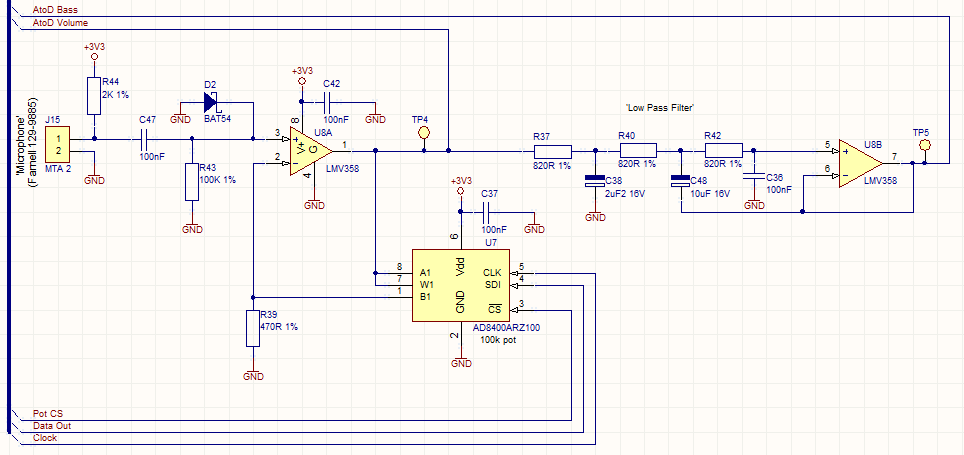
This circuit employs a digital potentiometer to enable the microcontroller to automatically adjust the circuit's gain according to the ambient audio volume. However, a standard potentiometer can be used if automatic adjustment is unnecessary. The low-pass filter design is...
Digital IC, Electronic Lock This is an electronic code lock that can function as a door latch or ignition key. The operation is somewhat complex, which contributes to the appeal of the circuit. The electronic code lock utilizes a digital...
One interface that is missing in the Lego MindStorms system is an electronic ear. This does not imply that the RCX should respond to spoken commands, which would require extensive electronics and software. Instead, it would be beneficial if...