
Two-tones Siren with IC 4093
The described circuit serves as an audio signal generator, specifically designed for entertainment purposes targeted at children. The circuit can be integrated into a variety of applications, such as bicycles, battery-powered vehicles, and toys, enhancing their play value through sound effects.
The core of the circuit consists of integrated circuits (IC1A, IC1B, IC1C, and IC1D), which function as oscillators to produce sound. The switch SW1 allows the user to select between two distinct sound modes. In one position, the circuit generates a dual-tone sound, reminiscent of emergency vehicles such as police cars or fire trucks. This is achieved through the interaction of the gates within IC1A and IC1B, which oscillate at specific frequencies to create the characteristic sound.
When SW1 is toggled to the alternate position, the circuit produces a siren-like sound that varies in frequency. This is initiated by pressing the pushbutton switch P1, which activates the oscillation of IC1C and IC1D. The frequency modulation of this siren sound provides an engaging auditory experience, as it starts at a higher frequency and gradually decreases, mimicking the sound of a distant siren.
The output of the circuit is amplified by transistor Q1, which drives a loudspeaker. It is recommended that the loudspeaker be of adequate size and enclosed properly to enhance sound quality and volume. The performance of the sound can be fine-tuned by adjusting the capacitance values of capacitors C1, C2, C5, and C6, as well as their associated resistors, allowing for customization of tone and duration of the sound effects produced.
Overall, this circuit design not only provides an enjoyable auditory experience but also encourages creativity and interaction in various play scenarios.This circuit is intended for children fun, and can be installed on bicycles, battery powered cars and motorcycles, but also on models and various games and toys. With SW1 positioned as shown in the circuit diagram, the typical dual-tone sound of Police or Fire-brigade cars is generated, by the oscillation of IC1A and IC1B gates.
With SW1 set to the other position, the old siren sound increasing in frequency and then slowly decreasing is reproduced, by pushing on P1 that starts oscillation in IC1C and IC1D. The loudspeaker, driven by Q1, should be of reasonable dimensions and well encased, in order to obtain a more realistic and louder output. Tone and period of the sound oscillations can be varied by changing the values of C1, C2, C5, C6 and/or associated r
🔗 External reference
Related Circuits
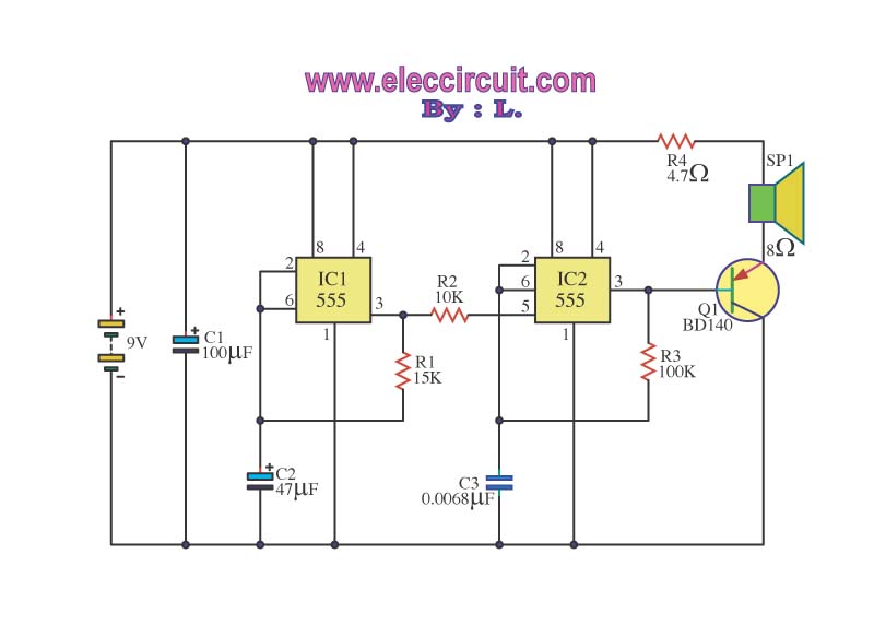
This circuit is a sound generator designed to simulate the siren of a British police car. It utilizes two timer IC 555 components to produce sound frequencies. The operation of the circuit involves the 555 timer on the right,...
The 555 timer on the right is configured as an alarm sound generator, while the second 555 timer on the left operates as a 1 Hz astable multivibrator. The output from the left timer modulates the frequency of the...
This circuit generates a sound akin to a police siren. It utilizes two 555 timer integrated circuits (ICs) configured as astable multivibrators. The frequency is regulated by pin 5 of the IC. The first IC operates at approximately 1Hz,...
The circuit under discussion is a four-siren sound generator utilizing the UM3561 integrated circuit (IC), which is a low-power CMOS device. Four distinct sounds can be generated by activating switches S1, S2, and S3. This circuit is versatile and...
The operation of the circuit is divided into three parts: low frequency production, high frequency manufacturing, and low frequency extension. The described circuit functions by segmenting its operation into three distinct sections, each serving a specific purpose in the overall...
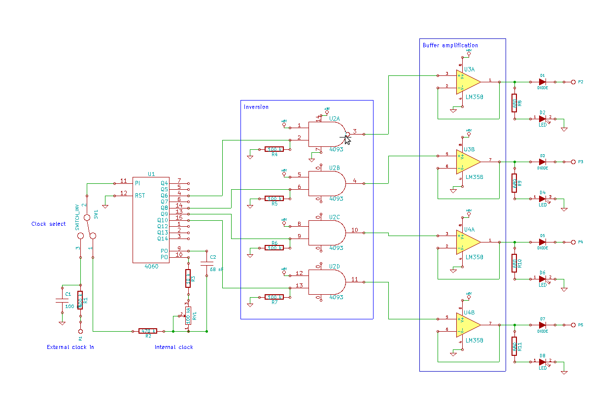
This blog showcases project documentation of various projects completed by members of the Association of Experimental Electronics. Some projects are beginner-friendly, while others are intended for more advanced solderers. The core components of this sequencer were assembled during the...