
Motor Control Circuit of LM339
The motor control circuit operates by employing the LM339, a quad comparator, to analyze the input control signal. When the signal is high, it triggers comparators A and A3, which in turn activate a power amplifier circuit formed by operational amplifier A4 and transistors VT5 and VT6. This configuration allows for efficient control of the motor M, ensuring it receives the necessary power to operate.
The inclusion of capacitance C1 serves a crucial role in the circuit by integrating the armature current, providing feedback to stabilize the motor's operation. The reset function of C1 is vital for maintaining accurate monitoring of the armature current, preventing overload conditions by ensuring that the current does not exceed safe operating limits.
The overall design emphasizes reliability and responsiveness, making it suitable for applications requiring precise motor control. The use of comparators allows for quick adjustments to the motor's power based on real-time input signals, while the feedback mechanism helps in maintaining consistent performance under varying load conditions. This circuit is ideal for automation and robotics where motor control precision is essential.The above picture is the motor control circuit composed of LM339 etc.When the input control signal is high PWL,comparator A and A3 make power amplifier conduct composed of A4,VT5 and VT6 and it drives motor M.At the same time,comparator also outputs and removes the armature current integral capacitance C1 reset.The armature current monitors the current e.. 🔗 External reference
Related Circuits
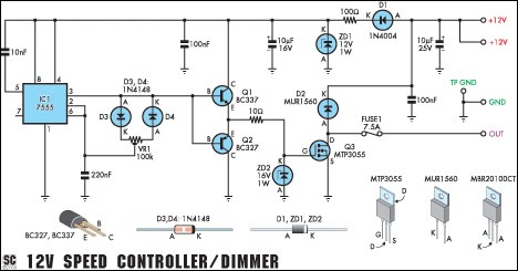
This circuit serves as a speed controller for a 12V motor with a continuous rating of up to 5A or as a dimmer for a 12V halogen or standard incandescent lamp rated up to 50W. It regulates power to...

A continuously operating wiper in a vehicle can be bothersome, particularly during light rain. The circuit outlined here allows for the adjustment of the wiper's sweeping rate, ranging from once per second to once every ten seconds. The circuit...
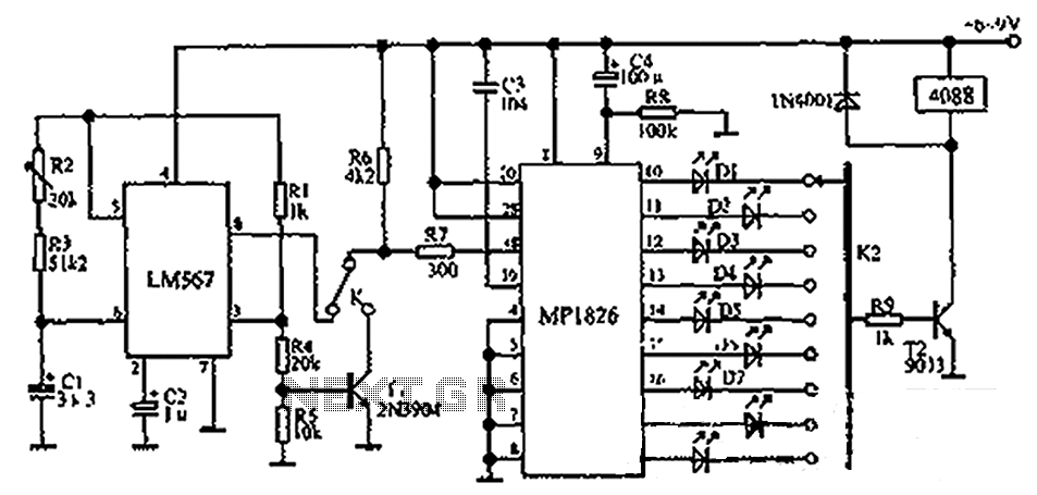
The circuit illustrated in the figure incorporates the MP1826 as a multi-stage divider. The LM567 serves as the frequency demodulation component, functioning as a dual-band oscillator that generates the desired low-frequency pulse from the MP1826. The oscillation center frequency...
The UBA2024 is a half-bridge integrated circuit (IC) and a 550 V lamp controller. This device features 9-ohm switches that support standard compact fluorescent lamp (CFL) applications up to 15 W. The UBA2024 is specifically designed for driving compact fluorescent...
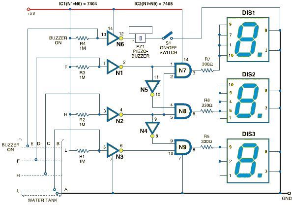
This schematic outlines a straightforward electronic project for designing a water level indicator circuit. It employs a 7-segment display to represent water levels in a tank as low, half, and full, indicated by the letters L, H, and F,...
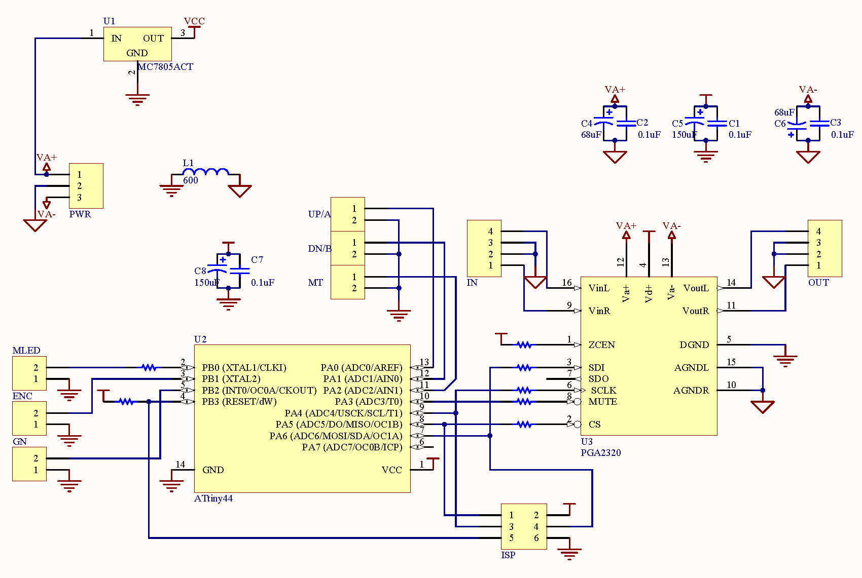
MiniVol is a straightforward volume control board utilizing the TI PGA2320 volume control IC, which operates over a range of -95.5 dB to +31.5 dB. It employs a small Atmel AVR microcontroller to manage the PGA2320 and allows users...