
20M Cw Transmitter Circuit
The transmitter circuit operates on the 20-meter amateur radio band, which spans frequencies from 14.000 MHz to 14.350 MHz. The VXO (Voltage Controlled Oscillator) circuit generates a stable frequency that is modulated to transmit signals. The keyed amplifier is designed to enable or disable the transmission, ensuring that the amplifier only operates during transmission periods, thus conserving power and reducing interference.
The MRF 476 final amplifier is a high-performance transistor that is capable of delivering 2 watts of output power. Its design allows for efficient amplification of the VXO signal, ensuring that the transmitted signal maintains clarity and strength. The output stage of the amplifier is crucial for achieving the desired transmission range and quality.
Incorporating a solid-state T-R (Transmitter-Receiver) switch is essential for seamless operation between transmission and reception modes. The solid-state design enhances reliability and minimizes switching noise, which is important for maintaining signal integrity during operation.
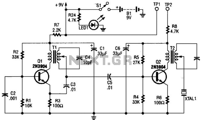
The component values indicated in the schematic are tailored for optimal performance within the 20-meter band, ensuring that the transmitter operates efficiently and effectively across the specified frequency range. Proper selection of components such as capacitors, resistors, and inductors is critical to achieving the desired frequency stability and output power. Adjustments may be necessary based on specific operating conditions or desired performance characteristics. The transmitter has a VXO circuit to drive an amplifier that is keyed. The keyed amplifier drives an MRF 476 final amplifier, which delivers about 2-W output. A solid-state T-R switch is included for the receiver. The parts values shown are for the 20-meter band. 🔗 External reference
Related Circuits
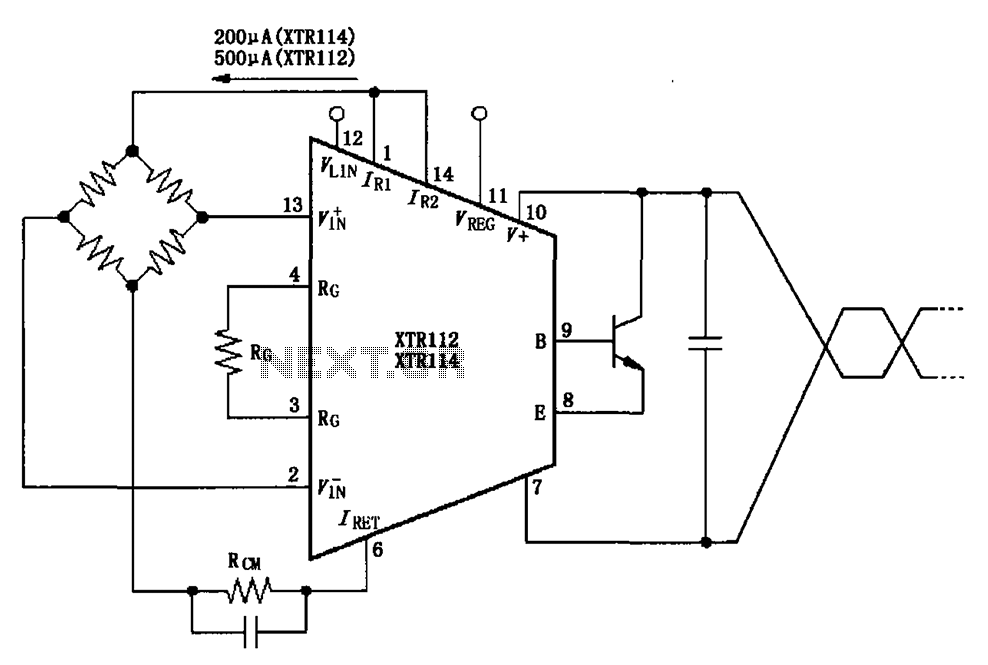
The two current sources within the chip (1 foot and 14 feet out) provide excitation. The output of each current source is 0.2 mA (XTR114) or 0.5 A (XTR112). The common mode input voltage is adjustable, ranging from 1.25...
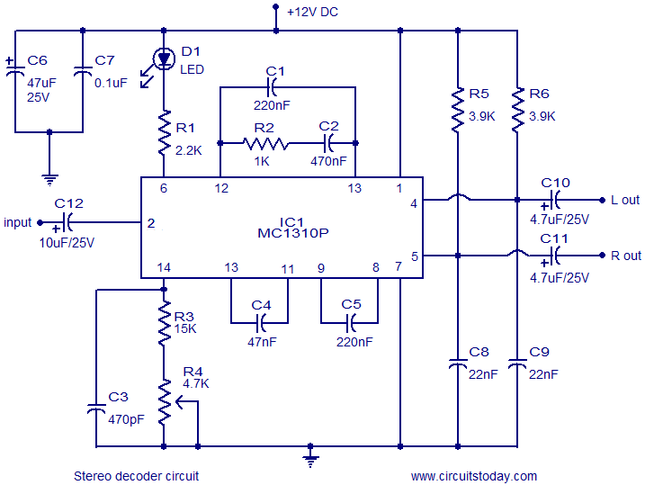
A simple FM stereo decoder circuit utilizing the MC1310P integrated circuit (IC). It operates at 12V and provides a channel separation of 40dB, making it suitable for stereo FM receivers. The FM stereo decoder circuit based on the MC1310P IC...
This is an intercom circuit that utilizes the LM380 as the audio amplifier and two transistors for the microphone preamplifier. The sound quality is sufficiently good while maintaining a low construction cost. The circuit comprises two identical intercom units,...
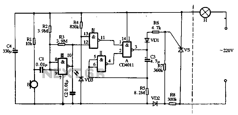
The main circuit utilizes a two-input NAND gate composed of four digital integrated circuits. This includes a NAND gate microphone amplifier circuit, a light control mechanism using an "AND gate," and a monostable delay control circuit formed by NAND...
Locker Guard Circuit Diagram. This compact circuit is designed to protect a locker or almirah from burglary. If the locker is opened while in the armed state, the circuit triggers a loud police siren to deter the burglary attempt. The...
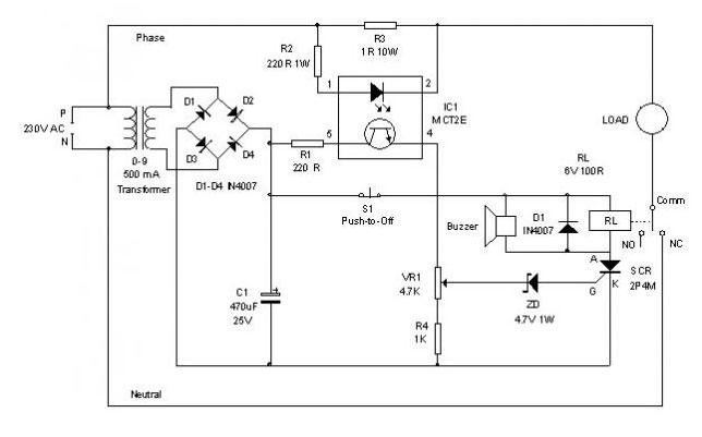
An electronic circuit breaker is designed to detect overload conditions and disconnect power when the load exceeds a predetermined threshold. This circuit is particularly suitable for safeguarding Uninterruptible Power Supply (UPS) devices, such as inverters. The electronic circuit breaker operates...