
Two way intercom circuit diagram using transistors and UM66 as ringer
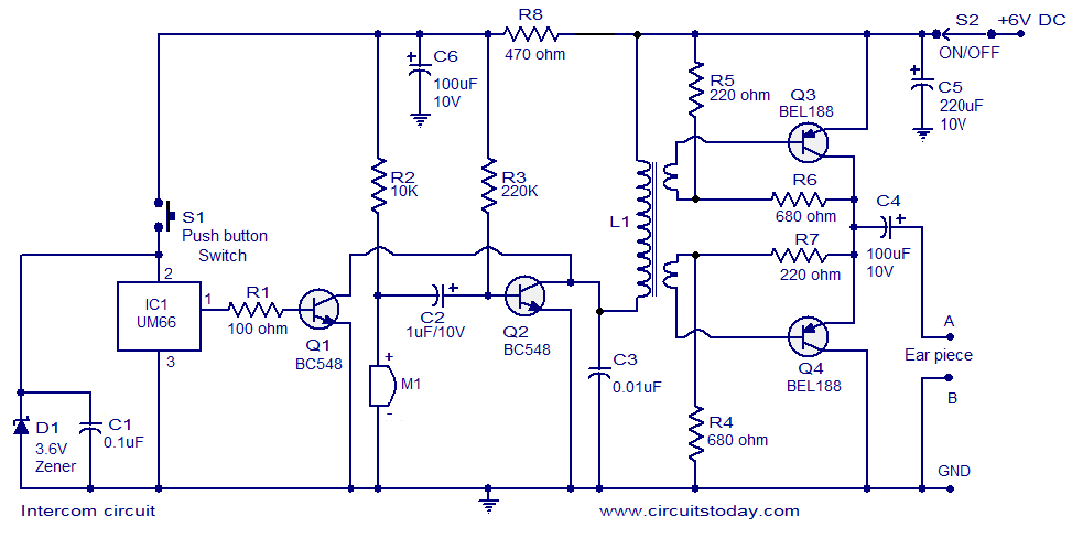
This intercom circuit utilizes transistors to facilitate communication between two or more stations without the need for complex switching mechanisms. The design typically consists of a transmitter and a receiver unit, where each unit is equipped with a transistor amplifier to enhance audio signals.
The circuit operates by converting the audio input from a microphone into an electrical signal, which is then amplified by the transistor. The amplified signal is transmitted through the wiring to the receiving unit, where another transistor amplifies the signal further before it is output through a speaker.
Key components of the circuit include:
1. **Transistors**: These serve as the main amplifying devices and are crucial for boosting the audio signals for clear communication.
2. **Microphone**: A standard electret or dynamic microphone can be used to capture the user's voice.
3. **Speaker**: A small speaker or piezo buzzer is employed to reproduce the audio signal at the receiving end.
4. **Resistors and Capacitors**: These passive components are used for biasing the transistors, filtering, and ensuring stability in the circuit operation.
5. **Power Supply**: A simple DC power supply (typically 9V or 12V) is required to power the circuit.
The simplicity of this intercom circuit makes it an excellent choice for basic communication needs, such as in homes or small offices. Its reliance on transistors allows for a compact design, making it easier to integrate into various environments without the need for extensive wiring or additional switching components. This circuit can also be modified or expanded by adding more units, allowing for multi-station communication.A very simple intercom circuit designed based on transistors. No need for a changeover switch and you can use it just like a telephone.. 🔗 External reference
Related Circuits
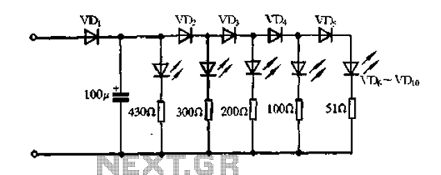
A passive light-emitting diode output level indication circuit. This circuit utilizes a light-emitting diode (LED) to provide a visual indication of the output level from a given source. The design is characterized by its passive nature, meaning it does not...
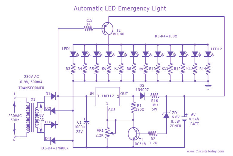
This is a cost-effective and straightforward emergency light circuit developed for CircuitsToday. It is an automatic emergency lamp with daylight sensing capabilities, meaning it detects darkness and turns on automatically, while also sensing daylight to turn off. The circuit...

The vehicle is a 1968 Ford equipped with a 1972 engine. The original alternator has been replaced with a new unit. It has been suggested that reversing the polarity of the voltage regulator is necessary for the alternator to...
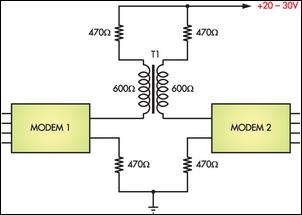
Connecting two PCs via modems using a twisted pair cable may not yield any results because the modems are designed to operate over a phone line. The scenario described involves the attempt to establish a connection between two personal computers...

This is a transistor tester integrated into a circuit or printed circuit board (PCB). It is utilized when a project does not function correctly, allowing for the testing of electronic components. The transistor tester is a crucial tool in electronic...
This circuit measures the distance covered during a walk. The hardware is located in a small box that can be slipped into a pants pocket. The display is designed such that the leftmost display, D2 (the most significant digit),...
Warning: include(partials/cookie-banner.php): Failed to open stream: Permission denied in /var/www/html/nextgr/view-circuit.php on line 713
Warning: include(): Failed opening 'partials/cookie-banner.php' for inclusion (include_path='.:/usr/share/php') in /var/www/html/nextgr/view-circuit.php on line 713