
1972 Ford V8 alternator wiring diagram and voltage regulator
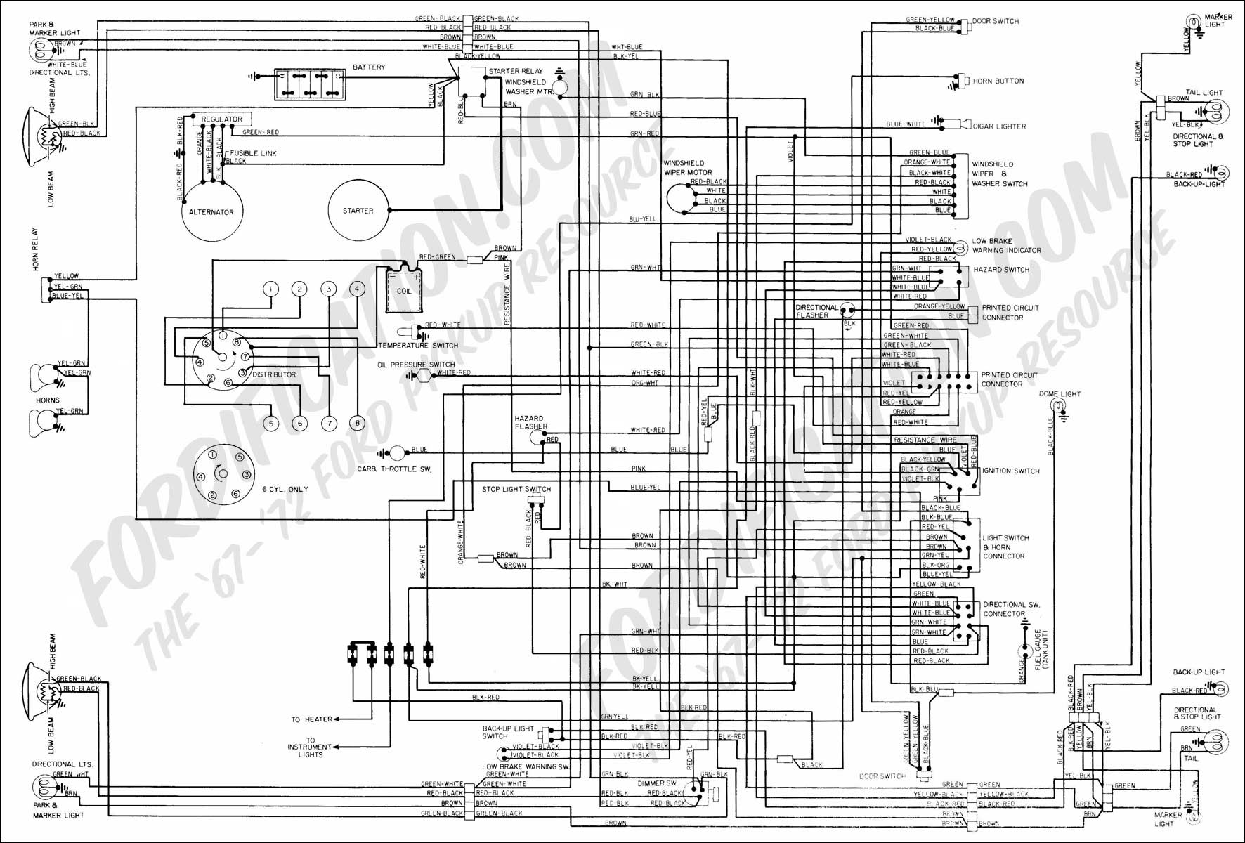
To create a functional electrical system in this 1968 Ford with a 1972 engine, it is essential to understand the interaction between the alternator and the voltage regulator. The alternator generates electrical power, which is then regulated by the voltage regulator to ensure a consistent voltage output to the vehicle's electrical system and battery.
In this scenario, the new alternator may be designed for a different polarity than the original setup. Typically, older systems, such as those in a 1968 Ford, operate on positive ground, while many modern alternators are negative ground. To accommodate this, the voltage regulator's polarity must be reversed. This adjustment allows the alternator to charge the battery effectively.
The wiring connections for the alternator typically include:
1. **B+ Terminal**: This terminal connects to the battery positive terminal, providing the alternator with the necessary voltage to charge the battery.
2. **Field Terminal (F)**: This terminal connects to the voltage regulator, controlling the alternator's output based on the battery's charge level.
3. **Ground Terminal (G)**: This terminal must be connected to the vehicle's chassis ground to complete the circuit.
For the voltage regulator, the connections are as follows:
1. **Battery Terminal (B)**: This terminal connects to the positive side of the battery to receive voltage input from the alternator.
2. **Field Terminal (F)**: This terminal connects to the alternator's field terminal, allowing the regulator to control the alternator's output.
3. **Ground Terminal (G)**: This terminal is connected to the vehicle's ground to ensure proper operation of the regulator.
A detailed wiring diagram should illustrate these connections clearly, showing the alternator's B+ terminal connecting to the battery, the field terminal connecting to the voltage regulator, and the ground connections to the chassis. It is also important to ensure that the voltage regulator is correctly oriented to reflect the reversed polarity, allowing for proper voltage regulation and safe operation of the new alternator.
In conclusion, careful attention to the wiring and polarity adjustments is crucial for the successful integration of the new alternator into the 1968 Ford with a 1972 engine. The provided wiring diagram will serve as a valuable resource for ensuring all connections are made correctly, facilitating reliable vehicle operation.I have 1968 Ford and the motor identification is now a 1972 engine. Alternator was gone and I have a new one. Was told that I need to reverse the polarity of voltage regulator to make alternator start charging. A diagram of wiring to both voltage regulator and alternator would help. 🔗 External reference
Related Circuits
This circuit diagram represents an indicator designed to display a battery voltage of 12 volts. The working principle involves comparing the battery voltage with a reference voltage using the LM324 integrated circuit, which is a low-power quad operational amplifier....
To set up the charging voltage, power on the charger and connect a voltmeter across the output terminals. Adjust R4 until the voltmeter reads 28V. The charger is now ready for battery connection. The charging circuit described involves a voltage...
These novel relay driver circuits have the capability to activate a relay with a coil voltage rating that is double the supply voltage (Vcc). Once the relay is activated, the armature is maintained using Vcc, resulting in a significant...
A digital camera has been purchased that is capable of capturing both images and videos. However, it has been reported that the camera has limitations related to battery life, which affects its operational duration. The digital camera operates using a...
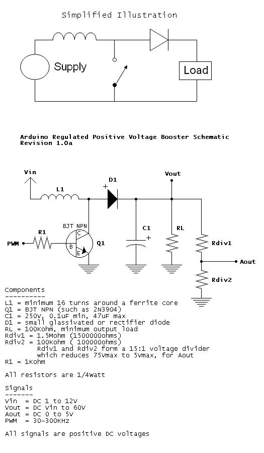
When Q1 is active, a larger current begins to flow through L1 to ground. When Q1 is switched off, the current through L1 tries to remain constant, resulting in an increased voltage. By varying the PWM duty cycle, the...
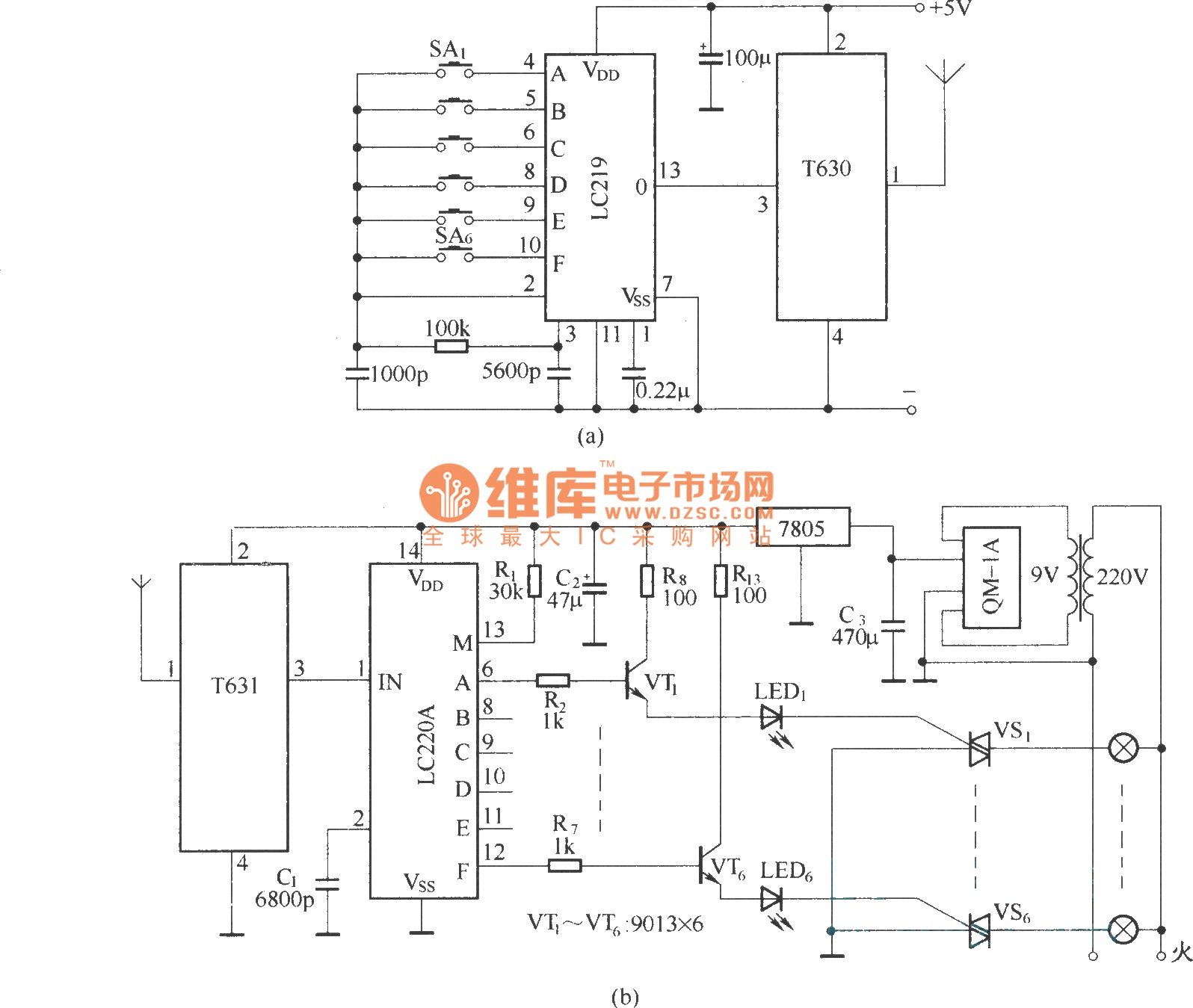
The circuit utilizes the long-wave wireless transceiver T630/T631 to manage a 6-channel load. It is characterized by low power consumption, high resistance to interference, and a simple structure. The circuit design incorporates the T630/T631 transceiver, which operates in the long-wave...
Warning: include(partials/cookie-banner.php): Failed to open stream: Permission denied in /var/www/html/nextgr/view-circuit.php on line 713
Warning: include(): Failed opening 'partials/cookie-banner.php' for inclusion (include_path='.:/usr/share/php') in /var/www/html/nextgr/view-circuit.php on line 713