
Two way Loudspeaker cross-over

The described loudspeaker system incorporates a passive cross-over network designed specifically for 8Ω loudspeakers. This network is crucial for optimizing sound reproduction by effectively dividing the audio signal into distinct frequency bands, ensuring that each loudspeaker operates within its optimal frequency range. The two-way configuration consists of a low-pass filter and a high-pass filter, which can be implemented using passive components such as inductors and capacitors.
The low-pass filter allows frequencies below a certain cutoff frequency to pass through to the woofer, which is designed to handle bass sounds effectively. The inductor in this filter provides impedance to higher frequencies, effectively blocking them from reaching the woofer. Conversely, the high-pass filter allows frequencies above a specified cutoff to be directed to the tweeter, which is optimized for high-frequency sounds. The capacitor in this filter blocks lower frequencies, preventing them from reaching the tweeter.
To ensure proper functionality, the design of the cross-over network must consider the impedance of the loudspeakers and the desired crossover frequencies. Calculating the values of the inductors and capacitors is essential to achieve the desired performance characteristics, including the slope of the filter and the transition between frequency bands. Additionally, the layout of the circuit should minimize signal loss and interference, which can be achieved by using short, direct connections and ensuring that the components are placed in a manner that reduces inductive and capacitive coupling between them.
In summary, the implementation of a two-way passive cross-over network for 8Ω loudspeakers enhances the overall audio experience by allowing for efficient frequency separation, thus optimizing the performance of both woofers and tweeters. This design approach not only improves sound quality but also extends the lifespan of the loudspeakers by preventing them from operating outside their specified frequency ranges.The resistance of loudspeakers is characterized in a frequency depending on the destination and their press. Loudspeakers are distinguished, as for the destination, in loudspeakers of low frequencies, woofer intermediate, mid-range and high tweeter.
Their resistance in W is 4W, 8W and 16W. Cross-over that we present it is intended for loudspeakers 8W. The loudspeakers are distinguished by various characteristics that him make distinguish between them. That characteristics that us interest for the manufacture that we make, are their complex or more simply resistance and diagram that us gives the relation of attribution of sound as for frequency (sensitivity).
Cross-over they are netting usually with passive materials that have aim to separate a region of frequencies in smaller. Cross-over the manufacture that to you we offer it separates the acoustic region in two sub areas in order to we lead two loudspeakers for the high frequencies and for low.
Cross-over they are essentially for the operation of combination of loudspeakers. Without them, two things happen: on one side are led all the frequencies simultaneously to different loudspeakers and otherwise is consumed pointlessly force in loudspeakers that cannot him attribute rightly. Cross-over depending on the number of loudspeakers that leads they are distinguished in two streets and three streets, even if they can result also complexes.
The each region is figuratively named street, through which will pass the corresponding region of frequencies in order to it leads the corresponding loudspeaker. The simpler system is that of two streets. In that acoustic region it is separated in two sub areas with two filters: one of low passage and one high.
The filter of low passage leads the loudspeaker for the low frequencies and the filter of high frequencies the loudspeaker for the high frequencies. The loudspeaker for the low frequencies is known as woofer and the loudspeaker for the high frequencies as tweeter.
🔗 External reference
Related Circuits
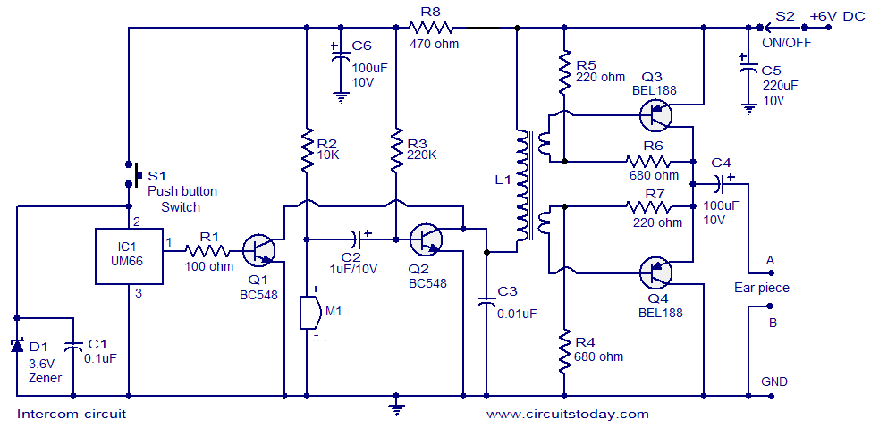
A straightforward intercom circuit designed using transistors. It does not require a changeover switch and can be used similarly to a telephone. This intercom circuit utilizes transistors to facilitate communication between two or more stations without the need for complex...
This system consists of two opto-isolated circuits that facilitate data transmission via an infrared network device between two computers. For instance, a user can transfer files from a desktop computer to a laptop computer without the use of cables,...
As with the Electronic sel. 8 we also have here a circuit with a choice of 8 different sources. The difference is that only two of the switches are used and the movement of commands is Up-Down in series....
This circuit was designed on request and can be useful to those wishing to have, say, a red LED illuminated when an appliance is on and a green LED illuminated when the same appliance is off. Any mains operated...
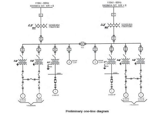
The single line diagram is a circuit diagram where a "one-line" representation illustrates the three phases of a three-phase power system. In addition to displaying the ratings and sizes of electrical equipment and circuit conductors, a well-drawn one-line diagram...
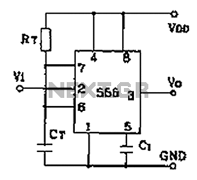
Common monostable circuit in two configurations: manual start type and start pulse type. It generates a single-shot pulse upon activation. A monostable circuit, also known as a one-shot multivibrator, is a fundamental electronic circuit that produces a single output pulse...