
A simple random number generator using 8051 microcontroller. AT89S51 is the controller used here

The circuit design for the random number generator based on the AT89S51 microcontroller involves several essential components and connections. The AT89S51 microcontroller, which is an 8-bit microcontroller from the 8051 family, serves as the core processing unit for generating random numbers.
The circuit typically includes a power supply, which provides the necessary voltage (usually 5V) to the microcontroller. A crystal oscillator, usually at a frequency of 11.0592 MHz, is connected to the microcontroller to establish the clock signal, ensuring the microcontroller operates efficiently.
Input peripherals, such as push buttons, can be included to trigger the random number generation process. These buttons are connected to the GPIO pins of the microcontroller, allowing user interaction. The output can be displayed on a 7-segment display or an LCD module, which are also interfaced with the microcontroller. The choice of output device depends on the design requirements and available components.
The program loaded into the AT89S51 microcontroller utilizes a pseudo-random number generation algorithm, such as the Linear Congruential Generator (LCG) or a similar method. This algorithm generates a sequence of numbers that approximates the properties of random numbers. The generated random number can then be processed further or displayed on the output device.
In summary, the random number generator circuit using the AT89S51 microcontroller is a straightforward yet effective project that illustrates the application of microcontrollers in generating random values, demonstrating both hardware and software integration in electronic design.Simple random number generator using 8051 microcontroller. AT89S51 is the controller used here.. 🔗 External reference
Related Circuits
PicCon is a PIC microcontroller based radio controller designed for hidden transmitter hunting. When combined with a radio transmitter, it will produce tone sequences and Morse code messages at user-programmed times. It is completely field programmable via DTMF tones,...
The heart of the lock is the 40022 octal counter. When first powered C2 is charged via R5 so the reset input of the counter is kept high. That causes output Q to go high while all the other...
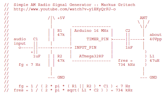
Markus constructed a software AM radio transmitter utilizing an Arduino. The audio signal is supplied to the ADC input via a decoupling capacitor. A PWM output pin directly controls a capacitor-inductor circuit connected to an antenna. The schematic and...

This is a simple 1.5V powered LED flasher circuit diagram. This circuit can flash 1.7V or 2.3V LEDs (depending on the color) using a 1.5V DC input. The LED will turn on when the 100µF capacitor is charged by...
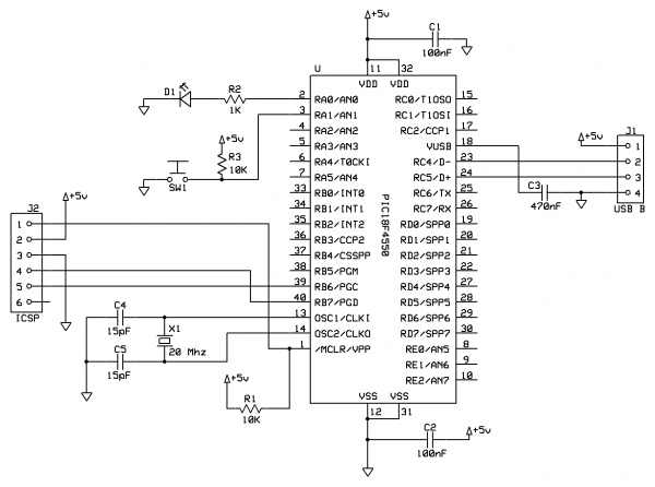
This tutorial provides guidance on creating a USB device, specifically a simple generic HID device using a breadboard. It covers the development of firmware for the PIC18F microcontroller and the creation of a Windows interface to control an LED...

A simple battery charger circuit with reverse polarity indication is presented here. The circuit utilizes the L200 integrated circuit (IC), which is a five-pin variable voltage regulator. The charging circuit can be powered by DC voltage from either a...