
Mobile Phone Travel Charger
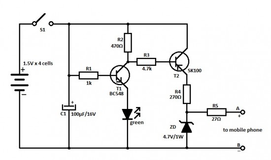
The mobile charger circuit is designed to be compact and portable, making it suitable for travel. It primarily consists of a battery holder for 1.5-volt pen cells, a voltage regulator, and a charging connector compatible with mobile phones. The circuit can accommodate multiple pen cells connected in series to achieve the necessary voltage output, typically 5 volts, which is required for charging most mobile devices.
The charger begins with the insertion of the pen cells into the holder, ensuring correct polarity to avoid damage to the circuit. The combined output voltage from the cells is then fed into a voltage regulator, such as the LM7805, which stabilizes the output to a consistent 5 volts. This regulator is essential for protecting the mobile phone from voltage fluctuations that could potentially harm its battery.
Additionally, a charging connector, such as a Micro USB or USB-C, is integrated into the design, allowing for easy connection to various mobile phone models. To enhance safety and efficiency, a diode may be included in the circuit to prevent reverse current flow, which could discharge the pen cells when the charger is not in use.
The performance of this charger allows for multiple recharges of a mobile phone battery, making it a reliable option for users on the go. The simplicity of the circuit also facilitates easy assembly and troubleshooting, making it accessible for hobbyists and engineers alike. Overall, this mobile charger provides a practical solution for maintaining device power during travel.Here is an ideal mobile charger using 1.5 volt pen cells to charge mobile phone while traveling. It can replenish cell phone battery three or four times in.. 🔗 External reference
Related Circuits
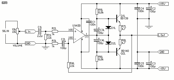
the AD844 was still used, but this time the feedback loop went all the way from output and back to input. The DC servo was removed and the current source was made faster, using an extra transistor. The local...
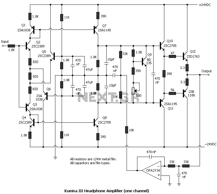
The amplifier is capable of delivering around 1.5W into 8 ohm headphones, and 2.2W into 32 ohms - this is vastly more than will ever be needed in practice. The use of a 120 Ohm output resistor is recommended,...
.png)
This document describes a simple engineering project circuit for a mobile cell phone detector (sniffer). This compact mobile communication detector can sense the presence of a mobile device, making it suitable for preventing mobile phone usage in private spaces,...
The USB charger power supply is designed for use in MP3 and MP4 chargers. It accepts an input of AC 160-240V at 50/60Hz and has a rated output of DC 5V at 250mA. For applications requiring a long-term higher...
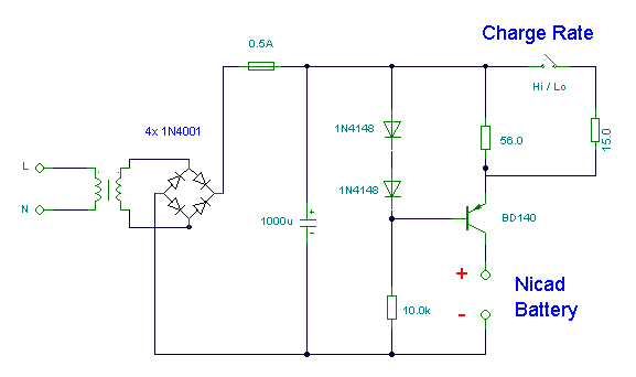
This simple charger utilizes a single transistor as a constant current source. The voltage across a pair of 1N4148 diodes biases the base of the BD140 medium power transistor. The base-emitter voltage of the transistor and the forward voltage...
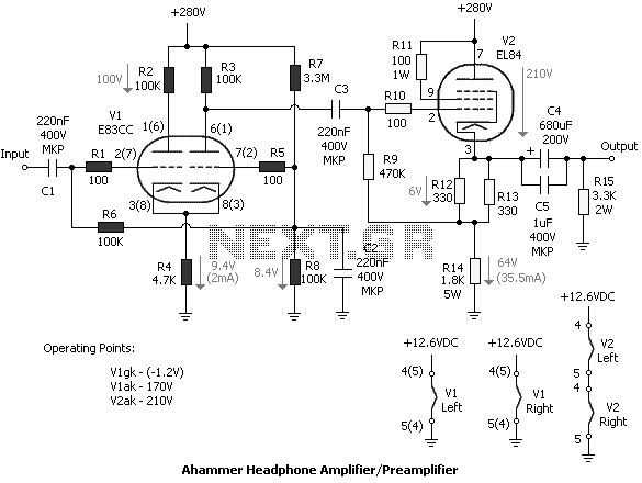
Tube amplifiers designed for headphones have the principal property that they can be used as preamplifiers too. In most cases, the output impedance of a tube headphone amplifier is (or should be) less than the output impedance of a...
Warning: include(partials/cookie-banner.php): Failed to open stream: Permission denied in /var/www/html/nextgr/view-circuit.php on line 713
Warning: include(): Failed opening 'partials/cookie-banner.php' for inclusion (include_path='.:/usr/share/php') in /var/www/html/nextgr/view-circuit.php on line 713