
uhf antenna amplifier booster
This UHF antenna amplifier circuit is designed to enhance the reception of UHF signals, making it particularly useful for applications where signal strength is weak or compromised. The choice of a single transistor design simplifies the circuit while still achieving a respectable gain of 15 dB, which is sufficient for most UHF applications.
The physical layout of the circuit is critical to its performance. By keeping the leads of the components short, the circuit minimizes parasitic capacitance and inductance, which can degrade signal quality. The recommendation to house the circuit in a waterproof case is essential for outdoor installations, as moisture can adversely affect electronic components and overall performance.
The inductors L1 and L2, being air-core coils, contribute to the circuit's high-frequency performance, as air-core inductors have lower losses compared to ferrite-core inductors at UHF frequencies. The specification of 2 turns of 0.5 mm enameled copper wire ensures that the inductance is appropriate for the desired frequency range while maintaining a compact form factor.
Inductors L3 and L4 serve as HF chokes, which are crucial for isolating the amplifier from the DC supply while allowing RF signals to pass through. The use of a ferrite core for these inductors enhances their inductance and current handling capability, ensuring stable operation across the specified frequency range.
The circuit's current consumption of 5 to 15 mA indicates its low power requirements, making it suitable for battery-powered applications or installations where power availability is limited. The choke coil used for power supply serves a dual purpose: it not only provides the necessary voltage to the amplifier but also acts as a filter to prevent any DC voltage from interfering with the TV signal, thus preserving the integrity of the amplified RF signals.
Overall, this UHF antenna amplifier circuit is a robust solution for enhancing UHF signal reception, with careful consideration given to component selection, layout, and environmental protection.This UHF antenna amplifier circuit or UHF antenna booster circuit can be used to amplify or boost the signal of UHF band from 400 MHz to 850 MHz. This circuit is using only single transistor and provides 15 db amplification. For best results keep all the leads of the components as short as possible and fit the circuit in a water proof case and ins
tall it near antenna. Shield the transistor from other components. L1 and L2 are equal to 2 turns of 0. 5mm enameled copper wire woud on 3mm former, both the coils are aircore. L3 and L4 are equal to 10uH HF choke or 0. 2mm 10 turns on ferrite core. The current consumption of the circuit is between 5 to 15mA. To power the circuit the voltage is fed through the cable by using a choke coil so it will prevent the DC voltage from entering in to the TV. 🔗 External reference
Related Circuits
Can be directly connected to CD players, tuners and tape recorders. Simply add a 10K Log potentiometer (dual gang for stereo) and a switch to cope with the various sources you need. A correct grounding is very important to...
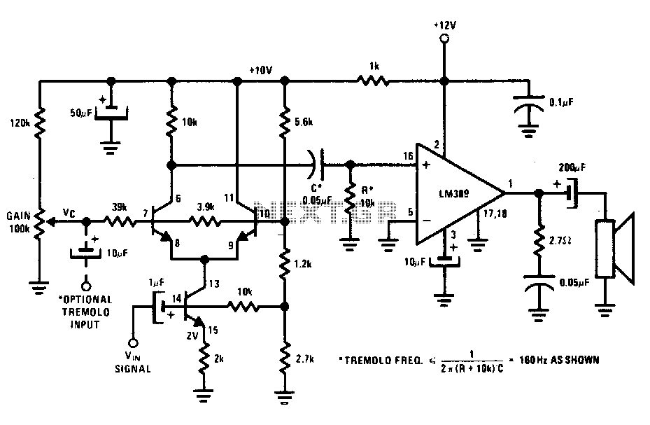
The transistors create a differential pair with an active current-source tail. This configuration, referred to as a variable-transconductance multiplier, produces an output that is proportional to the product of the two input signals. The multiplication effect arises from the...
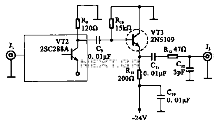
A high-frequency signal is displayed in the output amplifier. The circuit consists of a VI3 common collector amplifier (emitter follower) designed to enhance the child-band. It is a high-frequency amplifier (1-250 MHz) that increases the output voltage and boosts...
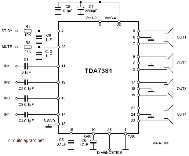
The amplifier is a quad amplifier circuit (amplifier with four inputs and four outputs) based on the TDA7381. This amplifier is designed for car audio systems, but it can also be utilized for other applications. The circuit has a...
This is an image Schematic. No Description available. The provided input indicates the existence of a schematic image without further descriptive content. In the context of electronic schematics, such images typically represent the arrangement and interconnection of various electronic...

This design outlines a simple wideband output amplifier suitable for use as a 50-ohm transmission line driver. The circuit is constructed using the CA3140 operational amplifier. When utilized alongside the function generator and sine wave shaper circuits, it delivers...