
Audio Quad Audio Amplifier Circuit diagram with TDA7831 4G—25W
The TDA7381 quad amplifier circuit is engineered to provide efficient audio amplification, particularly in automotive environments where space and power constraints are critical. The amplifier features four independent channels, each capable of delivering 25 watts of output power, making it suitable for driving multiple speakers in a car audio system. The architecture of the TDA7381 allows it to operate in class AB mode, which balances efficiency and audio fidelity, resulting in minimal distortion and improved sound quality.
The Flexiwatt25 package enhances thermal dissipation, allowing the amplifier to maintain performance under varying load conditions. The design eliminates the need for external bootstrap capacitors, simplifying the circuit layout and reducing component count. This characteristic is particularly beneficial in compact designs where PCB space is at a premium.
In addition to automotive applications, the versatility of the TDA7381 allows it to be integrated into various audio systems, including home audio setups, portable speakers, and multimedia computers. The circuit can easily interface with standard audio sources, such as MP3 players and computers, providing a robust solution for high-quality audio amplification.
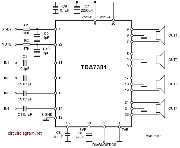
When constructing the circuit, attention should be paid to the power supply requirements, ensuring that the amplifier receives adequate voltage and current to operate efficiently. Proper heat sinking is also essential to prevent thermal overload, especially during extended use at high output levels. Overall, the TDA7381 quad amplifier circuit presents a reliable and effective option for a wide range of audio amplification needs.The afterward is a cloister amplifier ambit (amplifier with four inputs and four outputs) based TDA7381. This amplifier is advised for car audio system, but you can additionally use this ambit for added purposes.
This ambit has a architecture actual simple and actual accessible to build. The TDA7381 is a class AB audio power amplifier in Flexiwatt25 package designed for car radio applications. You may use the circuit for another application such as mp3 player, computer etc. Thanks to the fully complementary PNP/NPN output configuration the TDA7381 allows a rail to rail output voltage swing with no need of bootstrap capacitors.
Read more http://circuitdiagram.net/tda7381-4x25w-quad-audio-amplifier.html 🔗 External reference
Related Circuits
The bearing fault detection circuit comprises bearing detection sensors, a signal processing circuit, and a sound and light circuit. The signal processing circuit includes the input socket XS, a voice integrated circuit IC1, capacitors C1 to C3, resistors R1,...
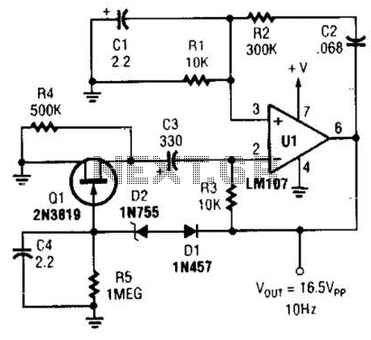
This Wien-bridge sine-wave oscillator utilizes a 2N3819 as an amplitude stabilizer. The 2N3819 functions as a variable-resistance element within the Wien bridge. The Wien-bridge oscillator is a type of electronic oscillator that generates sine waves. It employs a bridge circuit...
The thermostat can be set, and it specifies the lower limit of the circuit diagram. The thermostat in the circuit is a critical component used to regulate temperature by controlling the heating or cooling system. It operates by comparing the...
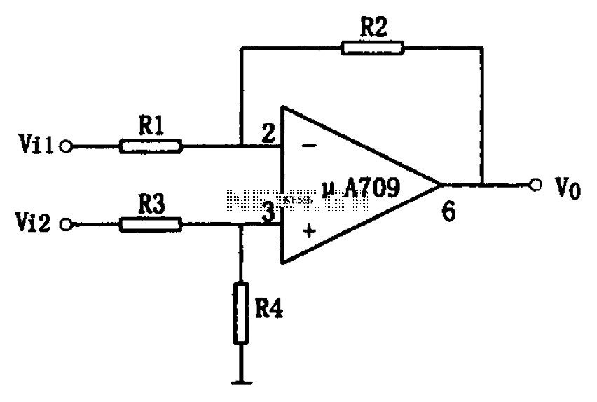
The simple differential amplifier circuit consists of two input signals, Vi1 and Vi2, which are connected through resistors R1, R3, and R4, forming a voltage divider circuit at the op-amp input. Vi1 is applied to the inverting input of...
A 2 µF capacitor is charged to approximately 340 volts, and the discharge is controlled by a silicon-controlled rectifier (SCR). A Schmitt trigger oscillator (74C14) and a MOSFET (IRF510) are utilized to drive the low-voltage side of a small...
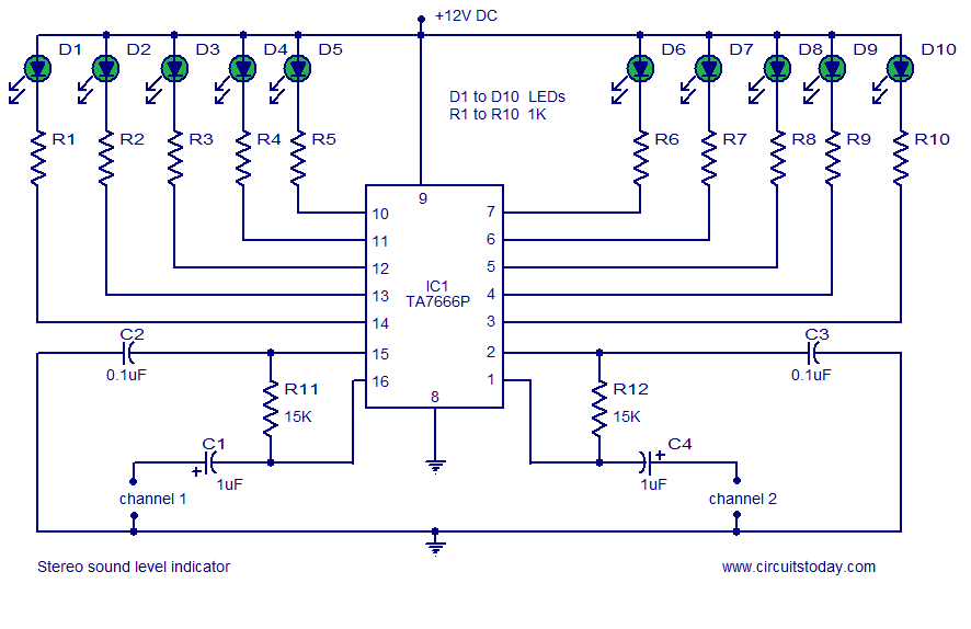
A stereo VU meter or 2-channel audio level meter utilizing the IC TA7666P. The volume level of each channel is indicated using 5 LEDs. This loudness meter requires a minimal number of external components. The stereo VU meter circuit is...