
Ultra-Flanger guitar effect
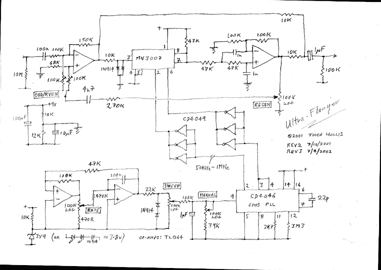
The circuit described is a flanger effect pedal that combines features from both the EH Electric Mistress and the MXR flanger, while also incorporating the wide sweep characteristic of the A/DA flanger. The design aims to achieve versatility and a rich sound palette, making it suitable for various musical applications. The inclusion of an additional integrated circuit allows for the extended sweep range, enhancing the modulation capabilities of the effect.
Power consumption ranges between 2 to 8 milliamps, which is efficient for a pedal of this nature, with the current draw primarily influenced by the clock frequency used in the modulation process. This low current consumption is advantageous for battery-operated applications and ensures longer operation without frequent battery replacements.
The circuit features a manual sweep function that allows users to control the modulation depth. A significant update noted in the development process indicates that the manual sweep circuit should connect to ground rather than a reference voltage (vref). This adjustment is crucial for correct operation and performance of the flanger effect.
Additionally, the feedback loop of the circuit is adjustable via a feedback limiting resistor, which was modified from 100K to 270K. This alteration is intended to refine the feedback characteristics, particularly the bass response within the flanger effect. The capacitor in series with this resistor plays a critical role in shaping the tonal qualities of the feedback signal, thus directly influencing the onset point of the flanging effect. Experimentation with this component can lead to variations in sound, allowing for a more personalized tone. Overall, this circuit represents a thoughtful balance of simplicity and complexity, catering to the needs of musicians seeking a versatile flanging effect.I was originally going to develop a minimum part count version of the EH Electric Mistress. Instead I went for a something with the versatility of an MXR flanger and the extra wide sweep that the A/DA flanger was known for. It needed an extra chip to get the wide sweep but it's worth it. Current consumption is very reasonable at around 2 to 8 milliamps dependent upon clock frequency. 7th April 2002: I have made a major correction to the schematic as a result of getting a second board going. The manual sweep circuit should return to ground not vref. I also increased the feedback limiting resistor from 100K to 270K. This area of the circuit might bear some experimentation as the cap in series with that resistor determines the amount of bass in the feedback signal which affects the onset point.
🔗 External reference
Related Circuits
The classic Rangemaster is considered a source of some of the finest tones in rock guitar, from Clapton's Beano sound to Brian May's singing sustain tones. Although the effect is a simple one-transistor booster, finding a high-quality germanium transistor...
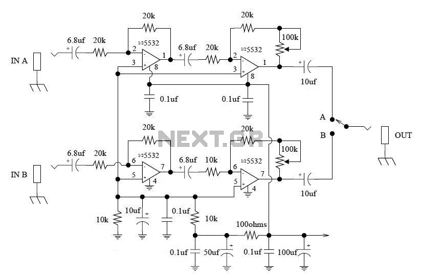
This A/B Box pedal schematic for electric guitar was designed by Rick Barker. The A/B Box effect was originally intended for switching between different harmonica microphones. It features a low-noise dual preamp for improved performance. The A/B Box schematic serves...
The schematic has been modified slightly to improve the tone control performance (04 Jan 2002). A new schematic is now on line - the differences are relatively minor, but make the component values for the tone controls a bit...
A guitar to MIDI interface was designed to serve as an interface between guitar playing and MIDI control of external hardware and software. This document describes the details of the design, experimentation, implementation, and final outcome of the project....
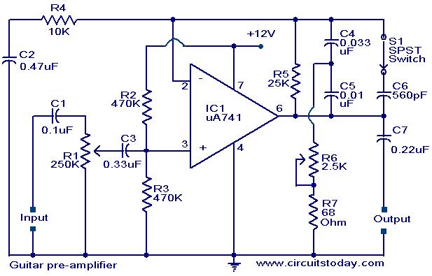
A preamplifier circuit designed for high-impedance electric guitar pickups is presented. This circuit utilizes a uA 741 operational amplifier (IC1) configured as a non-inverting amplifier. The potentiometer R1 functions as a volume control, while potentiometer R6 serves as a...
The Boss SD-1 Super OverDrive is a pedal characterized by a straightforward design, incorporating a dual operational amplifier (uPC4558C) and six transistors, along with an asymmetric overdrive circuitry that emulates the classic, natural growl of a tube amplifier. It...