
Ultrasonic Dog Repeller Circuit
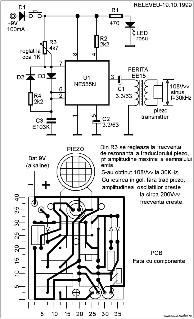
The ultrasonic dog repeller circuit operates by emitting high-frequency sound waves that are unpleasant to dogs but inaudible to humans. The core component of the circuit is the 555 timer IC, which is configured in astable mode to generate a continuous square wave output. This output drives the buzzer, producing ultrasonic frequencies typically ranging from 20 kHz to 40 kHz.
The circuit includes a ferrite transformer, which is used to amplify the signal generated by the buzzer, enhancing the range and effectiveness of the emitted sound waves. The transformer ensures that the high-frequency signals are efficiently transmitted, allowing the repeller to operate effectively over a distance.
Power supply requirements for the circuit can vary, but it is commonly powered by a 9V battery or a suitable DC power source. Proper decoupling capacitors should be included to stabilize the power supply and minimize noise that could affect the performance of the 555 timer.
For implementation, the circuit should be housed in a weather-resistant enclosure to protect it from environmental factors if used outdoors. An adjustable potentiometer can be incorporated to modify the frequency output, allowing customization based on the specific requirements of the user.
Overall, this ultrasonic dog repeller circuit provides a humane method of keeping aggressive dogs at bay, utilizing simple electronic components and well-established circuit design principles.This ultrasonic dog repeller circuit will chase away angry dogs. It is build with the all known 555 circuit, a buzzer and a little ferrite transformator. T.. 🔗 External reference
Related Circuits
The light from a flashlight is directed at a phototube, which activates a CMOS logic circuit powered by a battery. This circuit controls the switching action to turn the motor of a model train or other electric toys on...
This audio amplifier circuit is designed for use in classrooms to alleviate the strain of lecturing in noisy environments. It incorporates the power amplifier IC LM380, which delivers an output of 2 watts, adequate for confined spaces. The amplifier...
The following circuit diagram depicts a 100 Watt audio power amplifier, constructed using the LM3886 power amplifier chip. A single LM3886 IC can amplify audio power output up to 68W. In this circuit, two LM3886 chips are configured in...
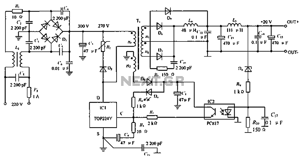
The circuit depicted in the figure is designed to achieve a higher power output by modifying specific components. On the left side of the figure, components R1, L1, D1, and capacitors C1 to C7 form a conventional filtering and...
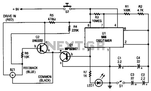
The electronic darkroom timer is constructed using a 555 oscillator/timer, a pair of general-purpose transistors, a buzzer, and an LED. The 555 timer (U1) is set up as an astable multivibrator, functioning as a free-running oscillator. The frequency of...
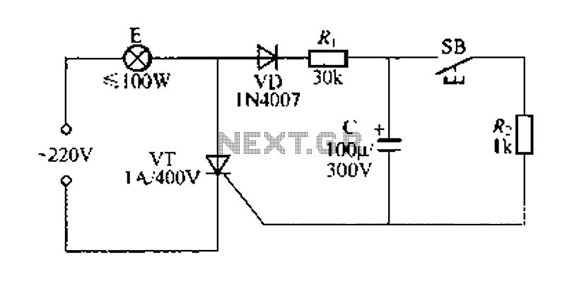
Figure 57 illustrates a simple delay lamp circuit that connects to lamp E using a two-wire connection. This design allows for the security bars to be installed directly, enabling replacement with a standard wall switch without altering the existing...
Warning: include(partials/cookie-banner.php): Failed to open stream: Permission denied in /var/www/html/nextgr/view-circuit.php on line 713
Warning: include(): Failed opening 'partials/cookie-banner.php' for inclusion (include_path='.:/usr/share/php') in /var/www/html/nextgr/view-circuit.php on line 713