
Simple delay lamp circuit 1
The delay lamp circuit operates effectively by utilizing a thyristor as a switching element, which is controlled by the charging and discharging cycle of the capacitor. The circuit's design allows for easy integration into existing systems without requiring extensive rewiring. The half-wave rectification provided by diode VD ensures that the AC voltage is converted to a usable DC voltage for triggering the thyristor, allowing for reliable operation.
The choice of components is critical in ensuring the circuit performs as intended. The capacitor C must not only withstand high voltages but also exhibit minimal leakage to maintain the required charge for the thyristor's gate. The resistor R plays a dual role by limiting the current to the gate of the thyristor and aiding in the charging of capacitor C. Additionally, the use of a resistor in parallel with the thyristor's gate can effectively manage any leakage issues that might arise, ensuring that the thyristor turns off as expected when the circuit is deactivated.
The design also considers the operational characteristics of the lamp. By allowing the lamp to operate on alternating current, the circuit reduces the intensity of the light emitted, which can contribute to a longer lifespan for the lamp. This is particularly advantageous in applications where longevity and reliability are essential, such as in security lighting systems.
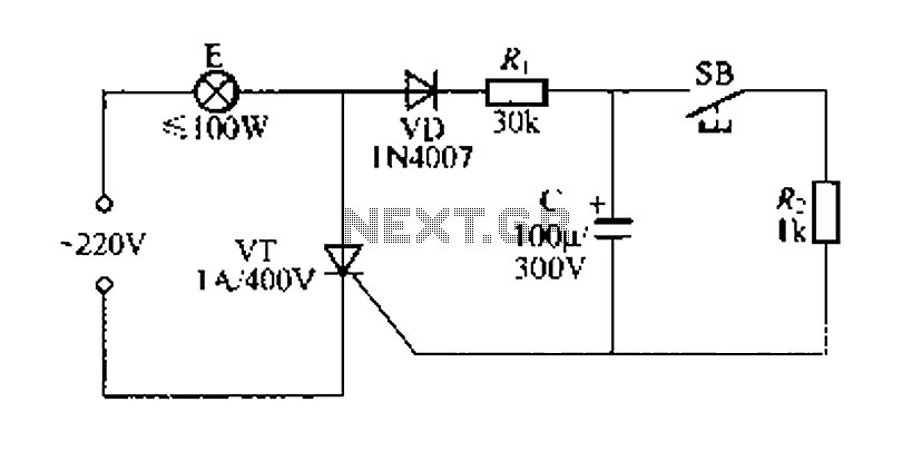
In summary, this delay lamp circuit is a practical solution for integrating lighting controls without significant modifications to existing electrical systems. Its design emphasizes safety, reliability, and efficiency, making it suitable for various applications where delayed lighting is desired.FIG. 57 is a simple delay lamp circuit, which is connected with the lamp E uses two-wire connection, so security bars when installed, can be directly replaced by an ordinary wa ll switch, without having to change the original interior wiring. When you press the key switch contact when SB, 220V AC by VD half crossing rectified, then by foot z R, thyristor VT applied directly to the gate, so that VT triggered the opening of the lamp E lights glow. Meanwhile, the charge stored in the capacitor C by SB product to bleed, after the release SB, power supply by VD, R.
To C charge, the charging current can be maintained VT continue to open, so the lights will not go out E. When C Kang full charge, VT off, lights E self-extinguishing. C should be resistant to high-voltage withstand voltage of 300V solutions capacitor, and the leakage current is small.
If the leakage current is relatively large, it may cause VT will not turn off. At this time, in VT gate between the cathode and a parallel resistor ikfl to solve, or choose trigger thyristor stream slightly larger, but the delay time will be shortened. Bong circuit when the lamp E lights flowing through the lamp current to alternating current BI Bo, the low light, but a longer lamp life.
Related Circuits
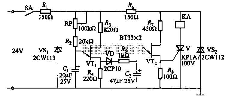
This circuit consists of three single-junction transistor time relay circuits utilizing a pulse charging mechanism, allowing for extended delay times of up to several minutes. The first stage delay circuit incorporates unijunction transistors (VTi) and other components, where capacitor...

The circuit employs a field-effect transistor (FET) at the input of a Schmitt trigger, allowing the use of a low-value capacitor. The trigger, controlled by Q1 and O2, exhibits a hysteresis of approximately 3V, regulated by a 3V zener...

This circuit is used for a Digital Radar Speedometer. It allows for the measurement of the speed of any moving object, particularly vehicles such as cars. The speed is displayed in kilometers per hour (KPH) with a three-digit display....
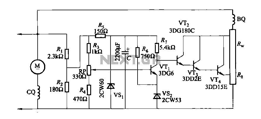
The DC generator automatic voltage regulator circuit is illustrated in Figure 7-53. This circuit is designed for a 40kW, 230V DC shunt complex machine, with a voltage change rate of up to 2.5 percent. In Figure 7-53, BQ represents...

This project outlines a simple remote control system utilizing RF communication without a microcontroller. The remote is designed to operate various home appliances such as televisions, fans, and lights, providing convenience by allowing users to control devices from a...
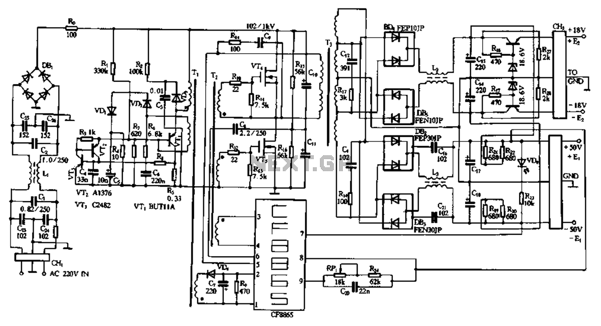
This document describes a specific module utilizing the CF8865 switching power supply circuit, which employs the integrated control module CF8865. In the figure, transistors VT4 and VTs are controlled by the excitation transformer Tz. The output is processed through...
Warning: include(partials/cookie-banner.php): Failed to open stream: Permission denied in /var/www/html/nextgr/view-circuit.php on line 713
Warning: include(): Failed opening 'partials/cookie-banner.php' for inclusion (include_path='.:/usr/share/php') in /var/www/html/nextgr/view-circuit.php on line 713