
Bright JOULE THIEF flashlight circuit
The Joule thief circuit is a minimalist, low-power boost converter designed to extract energy from low-voltage sources, such as depleted batteries. This circuit is particularly effective in applications where energy efficiency is critical, allowing for the utilization of energy that would otherwise be wasted.
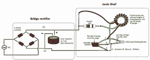
The core component of the Joule thief is a transistor, which acts as a switch. When the circuit is powered, the transistor rapidly turns on and off, creating a magnetic field in the inductor. This magnetic field stores energy and, when the transistor turns off, the collapsing field induces a voltage spike. This spike is then rectified and smoothed to provide a higher output voltage than the input.
The typical configuration includes a few essential components: a transistor (often a low-threshold NPN type), a resistor, an inductor, and a diode. The resistor is used to limit the base current to the transistor, ensuring it operates within safe limits. The inductor is chosen based on the desired output voltage and current, while the diode prevents backflow of current, protecting the circuit.
In a flashlight application, the Joule thief can significantly extend the life of batteries by allowing them to be fully utilized until they can no longer provide usable power. This is particularly advantageous for LED flashlights, which require higher voltages than what a single AA or AAA battery can provide when nearly depleted.
Overall, the Joule thief circuit exemplifies an efficient solution for low-voltage energy harvesting, making it an ideal choice for portable lighting applications where maximizing battery life is essential.Breathe down and come out on the bright flashlight. In order to promote the voltage, I have used pieces of highly skilled Joule thief circuit 🔗 External reference
Related Circuits
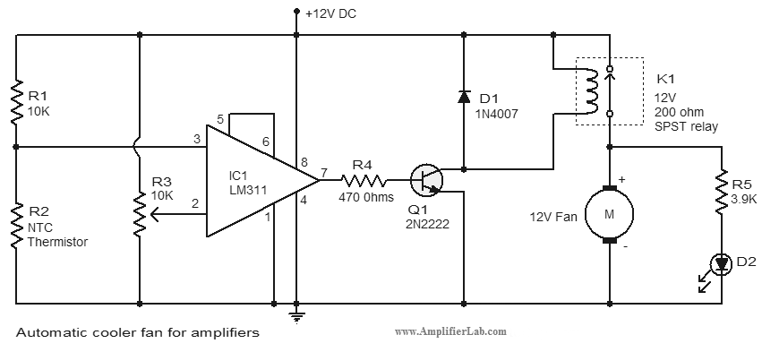
An automatic cooler fan for amplifiers is a circuit designed to conserve power in amplifier circuits. This circuit activates the fan. The automatic cooler fan circuit for amplifiers operates by utilizing temperature sensors to monitor the heat generated by the...
Adrian Bontenbal has provided updated notes from his experiments in recreating Clara Rockmore's theremin. Bob Moog shared his hand-drawn schematic for Clara's instrument over a decade ago. Adrian started with that schematic to build his own Rockmore theremin. During...
Capacitors C1 and C2, in conjunction with a speed controller, function by receiving voltage at the gate of the MOSFET. When the voltage on C is applied, it activates the operation of the MOSFET. In this circuit configuration, capacitors C1...
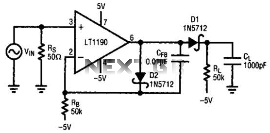
In this open-loop design, the detector diode is D1, and a level-shifting or compensating diode is D2. Load resistor RL is connected to -5 V, and an identical bias resistor RB is used to bias the compensating diode, also...
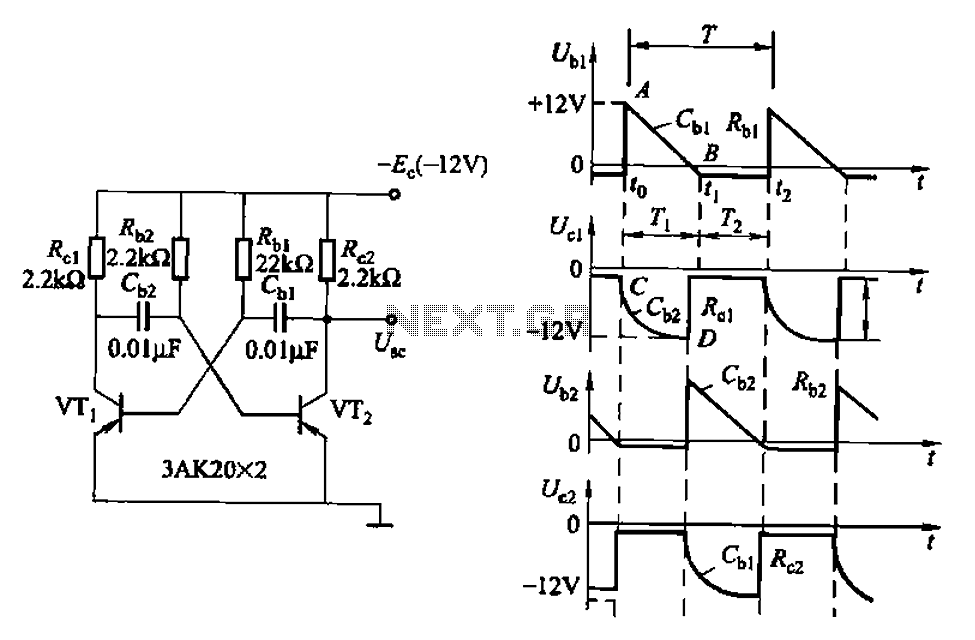
Also known as a no-shot multivibrator, this circuit is often utilized as a pulse (square wave) signal source. The astable flip-flop functions as a strong positive feedback amplifier, with its two branches coupled by an RC timing circuit, resulting...
The high durability of a light-emitting diode (LED) makes it suitable for ON/OFF indicator applications. However, there are limitations regarding low operating voltage. Light-emitting diodes (LEDs) are semiconductor devices that emit light when an electric current passes through them. Their...
Warning: include(partials/cookie-banner.php): Failed to open stream: Permission denied in /var/www/html/nextgr/view-circuit.php on line 713
Warning: include(): Failed opening 'partials/cookie-banner.php' for inclusion (include_path='.:/usr/share/php') in /var/www/html/nextgr/view-circuit.php on line 713