
Simple and practical human approach detector circuit diagram
The human body acts as an additional polar plate when in proximity to the copper-clad plate, resulting in an increase in capacitance as the individual approaches. This capacitance varies between 2 to 6 pF. The change in capacitance produces a pulse signal at the output of IC3, with the pulse duty cycle being directly proportional to the incremental capacitance. One output of the square wave from T2 is sent to comparator IC1B via resistor R3 and then to one input of XOR gate IC3 after amplification. The other output is first delayed by R1 and C1, amplified by comparator IC1A, and then sent to the second input of XOR gate IC3. Consequently, the duty cycle of the output square wave from XOR gate IC3 is directly proportional to the delay introduced by R1 in the input circuit. This configuration generates a direct current that correlates with the distance of the human approach, which is subsequently filtered by R6 and C4.
The human approach detector circuit is designed to sense the proximity of a human body through changes in capacitance. The oscillator circuit operates at 1 MHz, providing a stable frequency for the detection mechanism. The integrated operational amplifiers (IC1A and IC1B) play a crucial role in signal conditioning, amplifying the signals derived from the oscillator and the capacitive changes caused by human presence.
The XOR gate (IC3) serves as the final processing stage, where the two inputs—one from the direct oscillator output and the other from the delayed signal—are compared. This comparison results in a pulse signal whose duty cycle varies with the distance of the human approach, effectively translating the capacitive change into a measurable output.
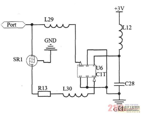
The filtering components (R6 and C4) ensure that the output signal is smoothed, removing high-frequency noise and providing a stable DC output that reflects the detected proximity. This output can be utilized in various applications, such as security systems, automatic lighting controls, or interactive devices that respond to human presence. The design emphasizes efficiency and reliability, making it suitable for a range of electronic applications requiring proximity detection.Human approach detector circuit is composed of integrated operational amplifier, gate circuit and resistor-capacitor unit in the diagram. Among them, 1MHz oscillator consists of reverser T1, 1MHz crystal oscillator and resistor-capacitor unit.
The oscillator signal is shaped by T2 and then T2 outputs square signal. It adopts a piece of 25cm2 copper clad plates to make up inductor. Human body is equal to another polar plate when human nears the copper clad plate. It can generate capacitance enlarge along with human`s approach and the capacity is 2~6pF. This incremental capacitance can make the after IC3 output pulse signal which pulse duty factor is proportional to incremental capacitance. One way of T2 outputted square wave is sent to comparer IC1B by R3, and is add to one input end of XOR gate IC3 after enlarged; another way is first delayed by R1 and C1, than enlarged by comparer IC1A and added to another input end of XOR gate IC3, thereby the duty factor of XOR gate IC3 outputted square signal is in direct proportion to the delay of R1 in the input circuit, then it generates DC current which is in direct proportion to the distance of human approach after filtered by R6 and C4.
🔗 External reference
Related Circuits
A thermistor is utilized in the circuit for heat sensing, while two 5K variable resistors are incorporated to calibrate the circuit for activating the relay at the desired temperature. The inclusion of a 1N4007 diode across the relay serves...
Due to the small size, high precision, and sensitivity of surface acoustic wave (SAW) sensors, along with their cost-effectiveness, a SAW gas sensor has been developed. This sensor comprises a surface acoustic wave device, a sensitive membrane, and the...
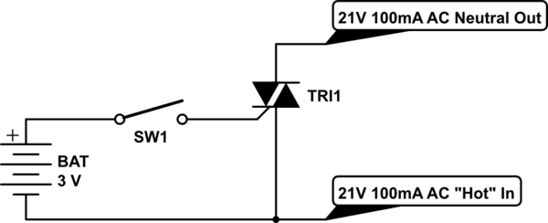
Control a furnace using a 3.3V microcontroller. The furnace operates by connecting a common 21V AC "hot" line to one of two AC "neutral" output lines: Fan and Heat. When connected, they have relatively low current flow, approximately 100mA....
Laser Command is a game developed using an 8x8 matrix LED and an Arduino Mini. It was created as a sample class project in the Gadgets, Sensors, and Activity Recognition course at Carnegie Mellon University, taught by Scott Hudson....
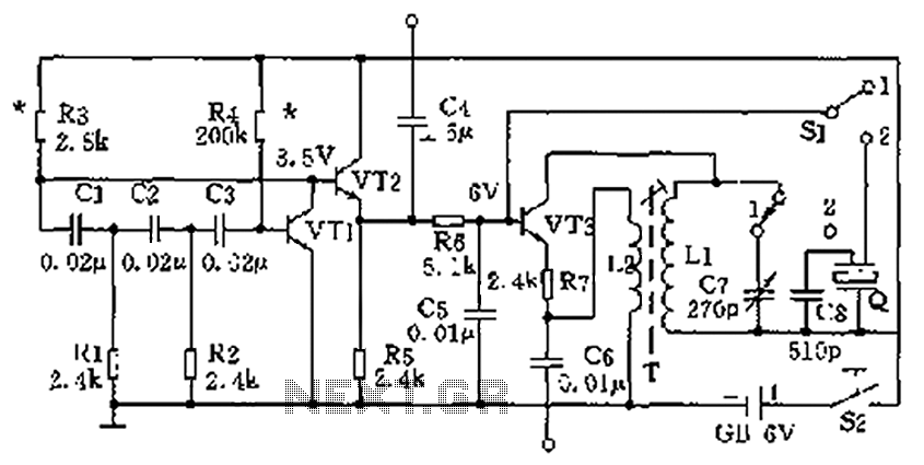
The high-frequency signal generator is designed to produce a low frequency of 1 kHz, an intermediate frequency (IF) signal of 465 kHz, and high frequencies ranging from 525 kHz to 1605 kHz. This device is particularly useful for radio...
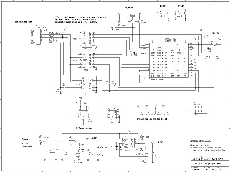
This GAL programmer is controlled via a parallel port, so that any exclusive interface is not required for the programmer. It is easy to use on the notebook PCs. When programming a PIC, a socket converter is needed. After...