
AC lamp Dimmer Schematic
More: A couple NPN transistors are used to detect the beginning of each half cycle and trigger a delay timer which in turn triggers the SCR at the end of the delay time. The delay time is established by a current source which is controlled by a 4017 decade counter. The first count (pin 3) sets the current to a minimum which corresponds to about 7 milliseconds of delay, or most of the half cycle time so that the lamp is almost off. Full brightness is obtained on the sixth count (pin 1) which is not connected so that the current will be maximum and provide a minimum delay and trigger the SCR near the beginning of the cycle. The remaining 8 counts increment the brightness 4 steps up and 4 steps down between maximum and minimum. Each step up or down provides about twice or half the power, so that the intensity appears to change linearly. The brightness of each step can be adjusted with the 4 resistors (4.3K, 4.7K, 5.6K, 7.5K) connected to the counter outputs. The circuit has been built by Don Warkentien (WODEW) who suggested adding a small 47uF capacitor from ground to the junction of the current source transistor (PNP) to reduce the digital stepping effect so the lamp will brighten and fade in a smoother fashion. The value of this capacitor will depend on the 4017 counting rate, a faster rate would require a smaller capacitor.
The described circuit is a dimmer for a 120V incandescent light bulb, utilizing a silicon-controlled rectifier (SCR) for phase control. The SCR allows for the modulation of the AC voltage supplied to the lamp, effectively controlling its brightness. The circuit begins with an AC power source, which is stepped down to a safe DC voltage using a 2K ohm, 10-watt power resistor. This resistor dissipates a significant amount of power (approximately 7 watts), necessitating adequate ventilation to prevent overheating.
The SCR is triggered by a timing mechanism that employs a pair of NPN transistors. These transistors detect the zero-crossing points of the AC waveform, initiating a delay timer that is crucial for determining the SCR's conduction time. The delay is controlled by a 4017 decade counter, which produces a series of counts that dictate the delay duration. The first output (pin 3) corresponds to the minimum delay, resulting in a nearly off state for the lamp, while the sixth output (pin 1) delivers maximum current, allowing the SCR to trigger early in the AC cycle for full brightness.
The counter provides additional outputs that facilitate incremental brightness adjustments. There are four resistors (4.3K, 4.7K, 5.6K, and 7.5K) connected to the counter outputs, which allow for fine-tuning of the current flowing through the SCR, thus enabling a smooth transition between brightness levels. The circuit's design incorporates a smoothing capacitor (47uF) connected to the junction of the current source transistor, which is a PNP type. This capacitor mitigates the abrupt changes in brightness, resulting in a more gradual and visually pleasing dimming effect.
Overall, this circuit effectively combines the principles of phase control, timing, and current adjustment to create a versatile dimming solution for incandescent lighting applications. Proper enclosure and safety precautions are essential when handling circuits connected to the AC power line to prevent electrical shocks.The circuit is directly connected to the AC power line and should be placed inside an enclosure that will prevent direct contact with any of the components. To avoid electrical shock, do not touch any part of the circuit while it is connected to the AC power line.
A 2K, 10 watt power resistor is used to drop the line voltage down to 9 volts DC. This resistor will dissipate about 7 watts and needs some ventilation. In this circuit, an SCR is used to slowly vary the intensity of a 120 volt light bulb by controlling the time that the AC line voltage is applied to the lamp during each half cycle. A couple NPN transistors are used to detect the beginning of each half cycle and trigger a delay timer which in turn triggers the SCR at the end of the delay time. The delay time is established by a current source which is controlled by a 4017 decade counter. The first count (pin 3) sets the current to a minimum which corresponds to about 7 milliseconds of delay, or most of the half cycle time so that the lamp is almost off.
Full brightness is obtained on the sixth count (pin 1) which is not connected so that the current will be maximum and provide a minimum delay and trigger the SCR near the beginning of the cycle. The remaining 8 counts increment the brightness 4 steps up and 4 steps down between maximum and minimum.
Each step up or down provides about twice or half the power, so that the intensity appears to change linearly. The brightness of each step can be adjusted with the 4 resistors (4.3K, 4.7K, 5.6K, 7.5K) connected to the counter outputs.
The circuit has been built by Don Warkentien (WODEW) who suggsted adding a small 47uF capacitor from ground to the junction of the current source transistor (PNP) to reduce the digital stepping effect so the lamp will brighten and fade in a smoother fashion. The value of this capacitor will depend on the 4017 counting rate, a faster rate would require a smaller capacitor.
🔗 External reference
Related Circuits
Approximately 20 years ago, small key-holders that emitted an intermittent beep for a few seconds upon detecting a whistle were quite common. These devices utilized a specialized integrated circuit (IC) that made them unsuitable for home construction. The current...
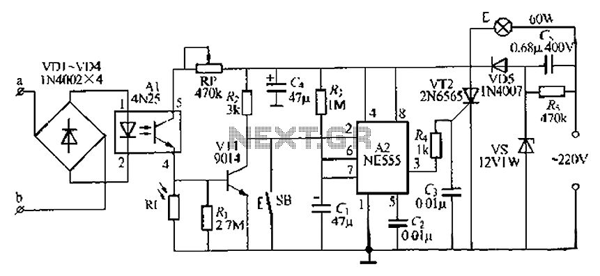
The lamp base circuit integrates an NE555 timer and optocouplers to automatically activate the light when a phone call is received at night. The lamp will self-extinguish after a delay. Additionally, a switch allows manual control of the lamp....
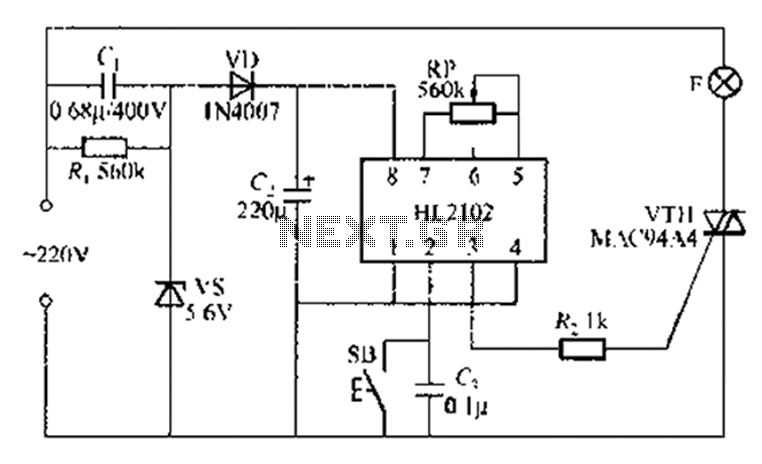
A thirty mining lamp control ASIC production delay lamp circuit is straightforward. It utilizes the HL2102 IC from Wuxi Love Core Microelectronics Co., Ltd. The circuit is designed to control a light with a timed delay, allowing for regular...
An audio compressor is designed to reduce the dynamic range of audio signals. The circuit diagram below illustrates a dynamic microphone compressor circuit that is straightforward yet delivers satisfactory results. The audio output is exceptional. This dynamic audio compressor...
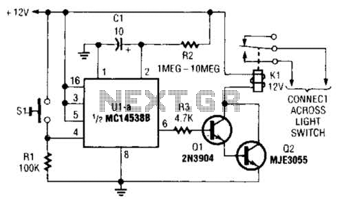
A normally open pushbutton switch (SI) provides a positive input pulse to pin 4 of U1, activating the integrated circuit (IC). The output from U1 at pin 6 delivers base-drive current to a Darlington pair consisting of Q1 and...
Schematic diagram. A presentation of the element-by-element relationship of all parts of a system. A schematic diagram serves as a crucial tool in electronic design and engineering, representing the interconnections and relationships between various components within a system. It provides...
Warning: include(partials/cookie-banner.php): Failed to open stream: Permission denied in /var/www/html/nextgr/view-circuit.php on line 713
Warning: include(): Failed opening 'partials/cookie-banner.php' for inclusion (include_path='.:/usr/share/php') in /var/www/html/nextgr/view-circuit.php on line 713