
Dimmer Switch

A dimmer switch is a device that allows for the adjustment of the brightness of a light fixture. It operates by varying the voltage and current supplied to the light source, which can be achieved through several methods, including phase-cut dimming, where either the leading or trailing edge of the AC waveform is clipped to reduce power to the load.
Installation of a dimmer switch typically involves replacing a standard light switch. This process requires turning off the power at the circuit breaker, removing the existing switch, and connecting the dimmer switch according to the manufacturer's wiring diagram. It is essential to ensure compatibility with the light bulbs being used, as not all dimmers work with all types of bulbs, such as incandescent, LED, or CFL.
In terms of circuitry, a basic dimmer switch consists of a control circuit and a power circuit. The control circuit includes a variable resistor or a microcontroller that adjusts the timing of the AC waveform, while the power circuit handles the actual load. Advanced dimmers may include features such as remote control, programmable settings, and integration with smart home systems.
Understanding the operation and installation of dimmer switches is crucial for ensuring optimal performance and compatibility with lighting systems. Proper selection and installation can enhance energy efficiency and provide a customizable lighting experience.Dimmer Switch - Dimmer Switch Working, Installation, Circuits and Explanation.. 🔗 External reference
Related Circuits
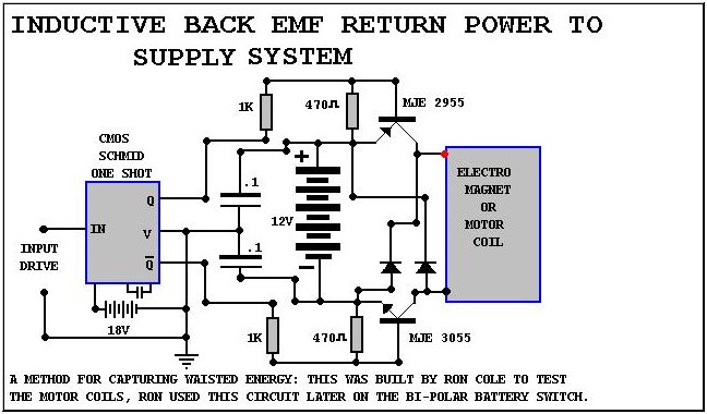
The starting point for the experiments was a switching device constructed by John Bedini for the Tesla Symposium. The objective was to enhance this switching device for compatibility with standard car or motorcycle batteries. The switching device designed by John...

This circuit is a touch switch circuit, similar to a touch door alarm. It utilizes a 555 timer as the core component of the touch switch circuit. The operation begins when the plate is touched, triggering the 555 timer....
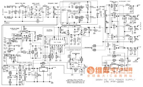
This example presents a switch DC regulated power supply circuit designed for buck-mode +5V applications. It consists of a power supply circuit, an impulsator, a voltage sampling or pulse width modulation circuit, and a buffering driver circuit, as illustrated...
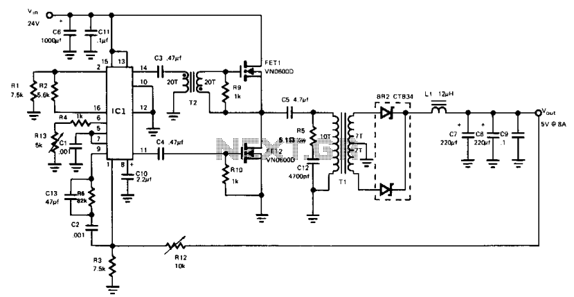
This buck-derived circuit delivers up to 8 A at 5 V DC while operating within an input voltage range of 24 to 32 V DC. The circuit utilizes two power MOSFETs that conduct alternately for equal durations. The switching...

This is a simple automatic light switch circuit designed for bedrooms. After construction, connect the input terminals of this circuit in parallel to the existing light fixture. The automatic light switch circuit operates using a photoresistor (LDR) and a transistor...
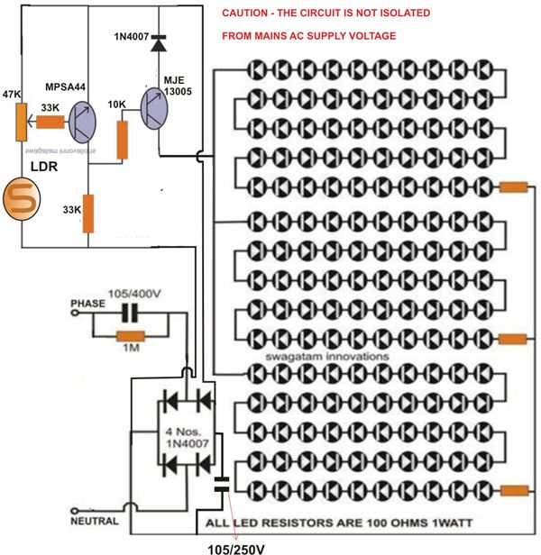
At times, it is quite frustrating to see street lights remaining switched on even during broad daylight. The current circuit for an automatic night light can effectively address this issue. This article explains how to construct such a system....