
Waterdrop device schematics

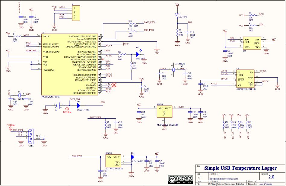
The electronic circuit described incorporates essential components for interfacing between an Arduino microcontroller and external devices such as a Shako valve, camera, and flash. The use of optocouplers is crucial for maintaining isolation between high-voltage components and the low-voltage microcontroller, thus preventing potential damage and ensuring reliable operation. The design emphasizes careful voltage management, particularly regarding the input and output voltages to avoid overheating the voltage regulators.
The circuit configuration allows for the integration of multiple optocouplers to accommodate various external devices, providing flexibility in the design. The optocouplers are connected to digital pins on the Arduino, enabling them to be controlled programmatically. The current limitations of the optocouplers necessitate consideration of the load they will handle, particularly when interfacing with older flash units that may operate at high voltages.
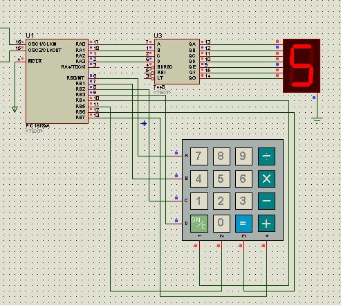
The inclusion of a matrix keypad enhances user interaction with the system, allowing for efficient input through a reduced number of pins. The voltage divider technique simplifies the design by allowing multiple button presses to be read through a single analog pin, streamlining the overall circuit complexity.
Overall, this electronic schematic is designed to facilitate the control of external devices while ensuring the protection and stability of the Arduino microcontroller, making it suitable for applications requiring precise control over multiple components.The Uno has just sufficient memory and ports. You have to program this one efficient in case you want to store settings in memory etc. Buying the Mega gives you more memory and ports. The Shako valve uses 24 volts DC. I would prefer to use 12 volts because it doesn`t heat the voltage regulators that much, but 24 volts will do the job. The Arduino cannot provide the power to activate the valve, therefore you need this electronic circuit: (check the connection pins of the TIP121 or compatible carefully. I don`t know if the pin numbers are correct in this drawing) Use 3 optocouplers oftype 4N25 or equalto trigger the flash and shutter.
The benefits of an optocoupler is an optical isolation between the flash- and cameracircuits from the electronic part of the microcontroller. The schematic created for 1 flash and 1 camera. The shutter requires two optocouplers (1 for autofocus and 1 for shutter. Even when you don`t use autofocus. You have to imitate the functionality of the shutter button of your camera which is half way press = autofocus and full press is shutter.
) The other optocoupler is to trigger your external flash. In case you need more flashes, just extend the schematic. Remember keep the electronic circuits of the microcontroller and camera and flash seperated from each other (so do not connect the GND between Microcontroller and/or Camera and/or flash. Each optocoupler is connected to one digital pin on the arduino. Making the pin high will turn on a led inside the optocoupler which makes the optical transistor inside the optocoupler to switch.
No other external power is necessary for the optocoupler to work. Build as many optocoupler circuits as devices (or switches) you need. An optocoupler can handle a very limited amount of current so don`t switch heavy currents. Modern flashes use about 6 volts to be triggered. Older flashes may use up to 300 volts which might damage the optocoupler. I don`t know if there are optocouplers that can handle this voltage, but I think they exist. The Arduino can handle voltages between 5 and 12 volts but only works stable between 7 and 12 volts (above 12 volts theonboardvoltage regulator will overheat). The input voltage of my system is 24 volts because I need 24 volts for the valve. I created 3 voltages in my system: The 9 volt is chosen because it`s within the limits of the Arduino Uno specs and I wanted a high as possible voltage to make the difference with 24 volts as little as possible.
(The bigger the difference, the hotter the regulator will be). I could choose 12 volts, but that is on the limit of the Arduino. The Arduino has its own voltage regulator and will output 5 volts on the digital pins which is perfect for all the other components like the optocouplers and so on. The 5 volt regulator is used to power external devices like a sound trigger. I didn`t want to load to much on the Arduino and this circuits costs a couple of euro`s. The voltage regulator used are a 7805 for 5 volts and the 7809 for 9 volts. Make sure you get the 1A version or even the 2A version. Mount a heatsink on the 780x component. A matrix keypadcan also be bought on ebay for a couple of dollars. Normally you need several digital inputpins to read the matrix. By using avoltage divider you only need 1 analog input. This works great even on a 16 button keypad. In software, read the value of the analog port while pushing a key. Then you know the approximate value that that specific keypress will provide. The pins on the keypad are probably 4 rows + 4 columns (or 4 col + 4 rows). Just use your multimeter to see which pins are connected when pushing a button. I used the 5 volts of the Arduino board to power` this matrix. I also build a sound detection interface to tr 🔗 External reference
Related Circuits

This circuit provides a regulated output voltage ranging from 5 V to 15 V DC, which can be adjusted using a preset resistor. The current output can reach up to approximately 350 mA. An integrated circuit is utilized to...

The electronic circuit illustrated in the figure consists of three main components: a voice recording module, an audio power amplifier, and a power supply circuit. The first component, IC1, is a voice recording integrated circuit (IC) of type PT-8815/20/30,...
The source code features a FAT12 filesystem that can be utilized to create custom flash drives for various projects. This source code is based on the Microchip Applications libraries for the Device Mass Storage SD Card data logger using...
Using a magnetic compass, ensure that both pickups have a South polarity on the top of each pickup. Verify this by checking for a North polarity on the bottom of the pickups. It is uncommon to find both pickups...
A keyboard key functions by establishing an electrical contact between the surface of the keyboard and the underlying circuit when the keytop area is pressed. This mechanism was utilized by some home computers in the early 1980s and has...
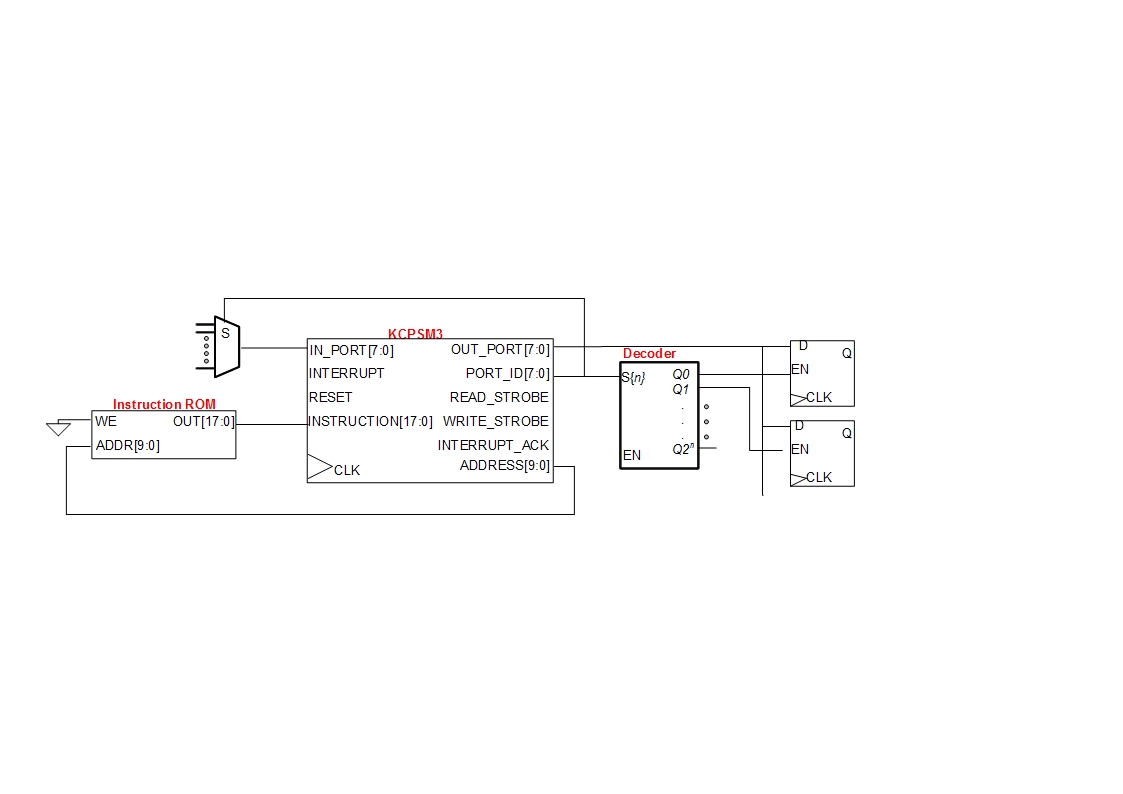
A small digital design utilizes a Xilinx Picoblaze softcore processor. Creating acceptable quality schematics has proven to be frustrating and time-consuming. Previous attempts to integrate existing schematics from LTSpice or Eagle into the documentation yielded unsatisfactory results, appearing fuzzy...