
Ultrasound Sensor

The Ping ultrasonic range finder operates on the principle of echolocation, emitting ultrasonic sound waves and measuring the time it takes for the waves to reflect back from nearby objects. This device is particularly effective for measuring distances in the range of 2 cm to 3 m, making it suitable for applications such as obstacle detection and distance measurement in robotics and automation.
To integrate the Ping sensor with an Arduino board, the following connections must be established: the 5V power pin of the Ping sensor should be connected to the 5V output pin of the Arduino, providing the necessary power for the sensor's operation. The GND pin of the Ping must be connected to a ground pin on the Arduino to complete the electrical circuit. The SIG pin, which transmits the signal back to the Arduino, is connected to digital pin 7.
The operation begins when the Arduino sends a short pulse to the SIG pin, which triggers the Ping sensor to emit an ultrasonic pulse. The Arduino then uses the pulseIn() function to measure the duration of the pulse that returns to the SIG pin. This duration is critical, as it represents the time taken for the sound waves to travel to the object and back. The speed of sound in air is approximately 343 meters per second; thus, the distance can be calculated using the formula:
Distance = (Time * Speed of Sound) / 2
The division by 2 accounts for the round trip of the sound wave. This method allows for precise distance measurements, enabling various applications in robotics, automation, and other fields where proximity sensing is required. The simplicity of the setup, combined with the effectiveness of the Ping sensor, makes it a popular choice for hobbyists and professionals alike.The Ping) is an ultrasonic range finder from Parallax. It detects the distance of the closest object in front of the sensor (from 2 cm up to 3m). It works by sending out a burst of ultrasound and listening for the echo when it bounces off of an object. The Arduino board sends a short pulse to trigger the detection, then listens for a pulse on th e same pin using the pulseIn() function. The duration of this second pulse is equal to the time taken by the ultrasound to travel to the object and back to the sensor. Using the speed of sound, this time can be converted to distance. The 5V pin of the PING) is connected to the 5V pin on the Arduino, the GND pin is connected to the GND pin, and the SIG (signal) pin is connected to digital pin 7 on the Arduino.
🔗 External reference
Related Circuits
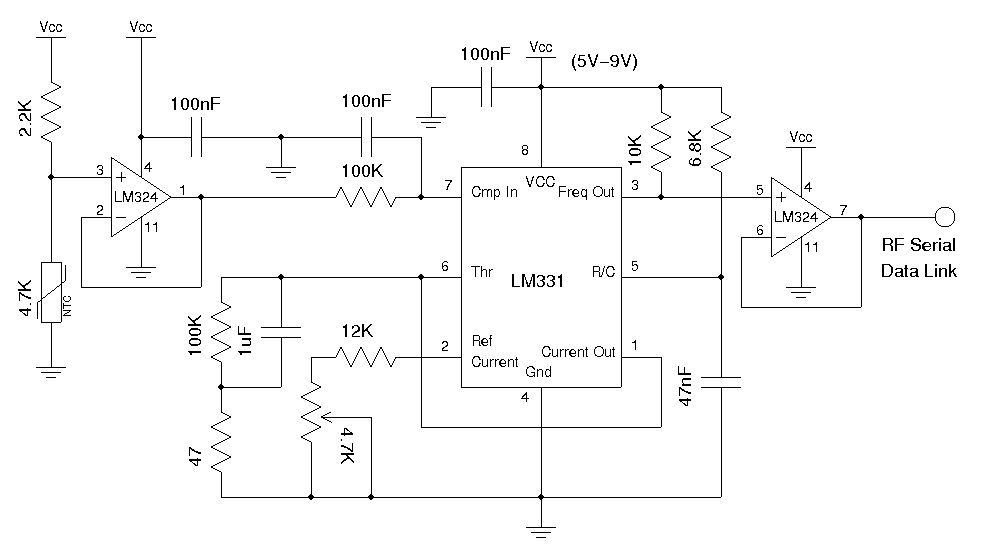
A wireless temperature sensor allows temperature measurements to be taken anywhere within the range of the transmitter and receiver. One straightforward approach to achieve this is by utilizing a voltage-to-frequency conversion chip in conjunction with an analog temperature sensor,...
Install the PIR module hanging from a 3-meter high mast to cover a 10-meter radius area. Connect its supply and relay terminals to the finished and enclosed circuit, ensuring the correct polarity is observed. A 4-core screened cable can...
XTAL1 drives amplifier Q3/Q4, which is tuned to 2.25 MHz. The detected signal is fed to audio amplifier IC1. A 9-V supply is used. The circuit operates at 2.25 MHz and is designed to be used with an ultrasonic...

A biaxial magnetic field sensor application circuit is illustrated in the figure. This circuit utilizes a biaxial magnetic sensor HMC1002 along with two AMP04 operational amplifiers (A1, A2) to measure the magnetic field in both the X-axis and Y-axis...
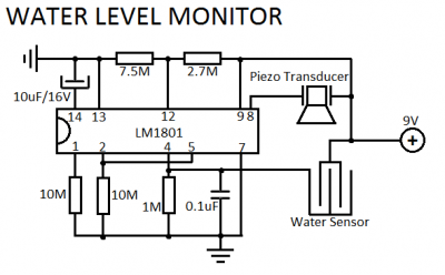
LM1801 Water Level Sensor Circuit Diagram. Features: reference voltage is overshot, and the IC drives the ceramic transducer to beep, low power consumption. The LM1801 water level sensor circuit utilizes the LM1801 integrated circuit, which is designed to monitor water...
I decided to make a commercial surface mount PC board using the LED2 sensor concept. It is quite sensitive and can track to a few degrees of accuracy in bright sunlight. If a blocking shadow is used the accuracy...