
LM1801 Water Level Sensor

The LM1801 water level sensor circuit utilizes the LM1801 integrated circuit, which is designed to monitor water levels with high precision. This circuit operates by generating a reference voltage that is critical for detecting the water level. When the water level falls below a predetermined threshold, the reference voltage is exceeded, triggering the integrated circuit to activate a ceramic transducer. This transducer emits a beep sound, providing an audible alert to indicate the low water level condition.
The circuit is designed for low power consumption, making it suitable for battery-operated applications. The LM1801 is capable of functioning effectively in various environmental conditions, ensuring reliable performance. The schematic typically includes essential components such as resistors, capacitors, and the ceramic transducer, all working together to form a complete water level detection system. Proper layout and component selection are crucial for minimizing noise and ensuring accurate sensor readings. Overall, the LM1801 water level sensor circuit is an efficient solution for monitoring water levels in a variety of settings, including aquariums, water tanks, and industrial applications.LM1801 Water Level Sensor Circuit Diagram. Features: reference voltage is overshot and the IC drives the ceramic transducer to beep, low power .. 🔗 External reference
Related Circuits
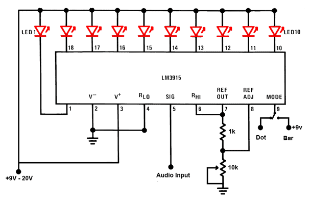
This is a simple audio sound level LED display circuit diagram. The circuit is entirely based on a single integrated circuit, the LM3915 from National Semiconductor. The LM3915 is a monolithic integrated circuit that displays the audio sound level...
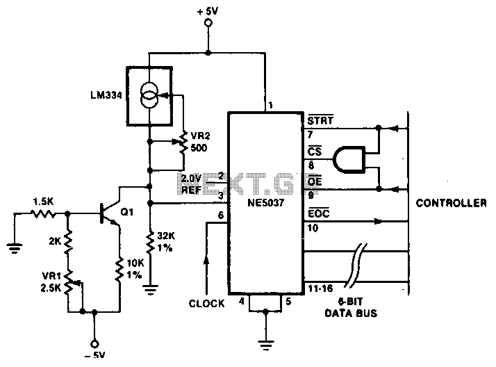
The temperature sensor provides an input to pin 3 of the NE5037 with a sensitivity of 32 mV/°C. This 32 mV represents the value of one least significant bit (LSB) for the NE5037. The LM334 is a three-terminal temperature...
It's basically a photovore with a couple tactile sensors. It's rather complex but can give neat behaviors with modifications to the circuit. At this point I don't have any plans to give more information on this circuit so your...
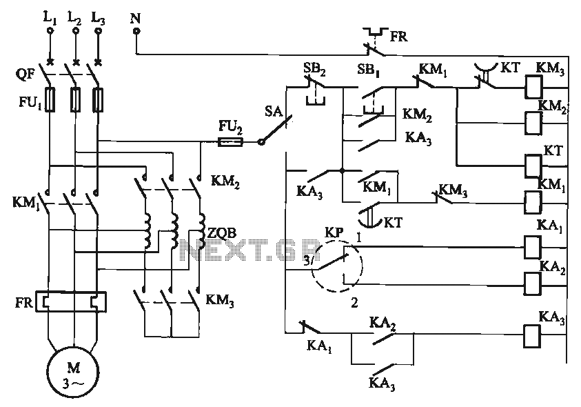
The circuit utilizes a motor auto-voltage transformer for starting. The motor auto-voltage transformer start circuit is designed to provide a controlled method for initiating the operation of an electric motor. This type of circuit is particularly beneficial in applications where...
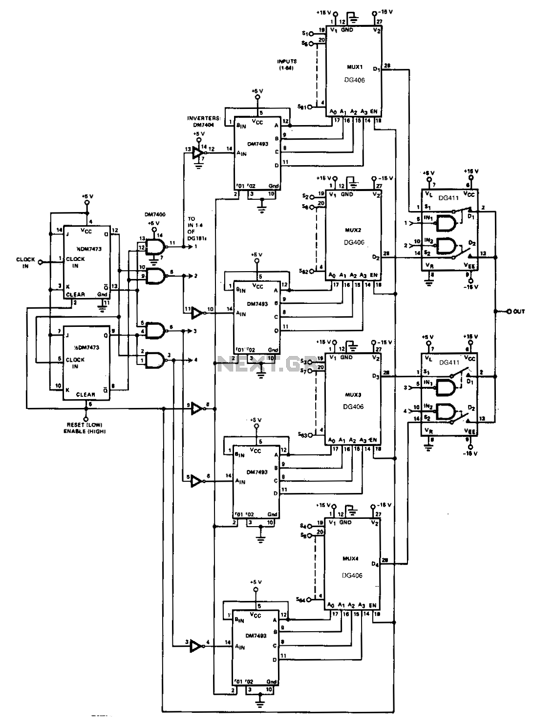
When a large number of channels are multiplexed, the outputs of two or more multiplexers can be connected together, and each multiplexer can be enabled sequentially. In the inhibit mode, the multiplexer consumes less power, and its output and...
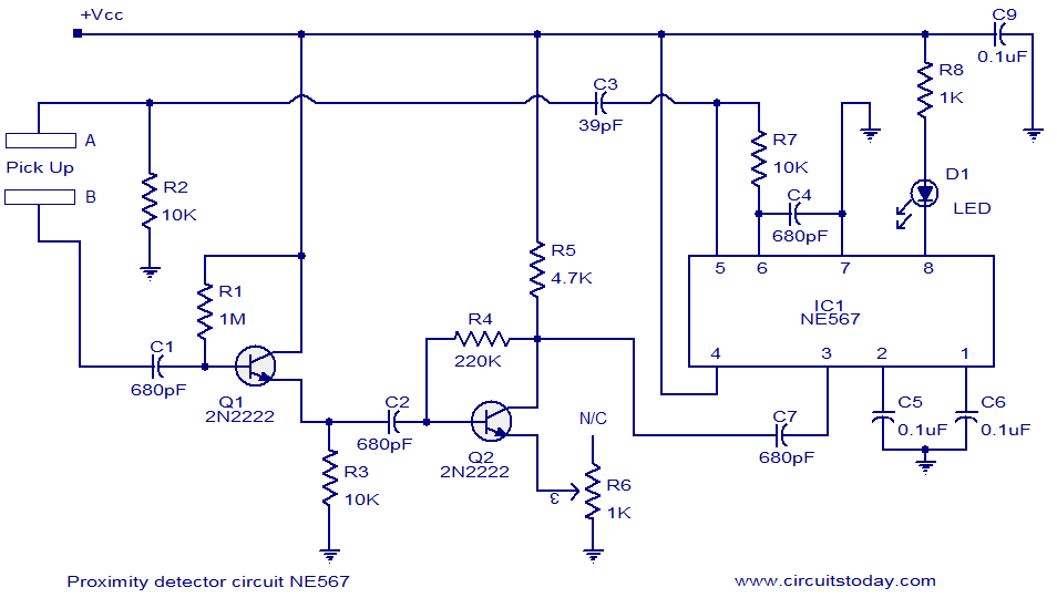
A simple proximity detector circuit utilizing the NE567 integrated circuit (IC). The circuit activates an LED when an object approaches the sensor. The NE567 is a versatile phase-locked loop (PLL) device commonly used for applications such as proximity detection due...