
Under-Temperature Switch
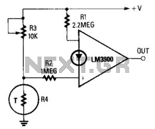
In this circuit configuration, the primary function is to establish a reference current that is stable and accurately reflects the supply voltage. Resistor R1 is critical as it sets the reference level for the inverting terminal of the operational amplifier (op-amp). The inverting terminal receives this reference current, which is essential for the proper functioning of the feedback loop.
The variable current, derived from the junction of R3 and R4, serves to adjust the output of the op-amp based on the desired trip temperature. R3 and R4 form a voltage divider, allowing for fine-tuning of the input to the non-inverting terminal. The relationship between R1, R2, R3, and R4 ensures that the circuit can maintain a consistent trip temperature regardless of fluctuations in the supply voltage. This characteristic is particularly important in applications where temperature stability is critical, such as in temperature sensing or thermal management systems.
The ratio of R1 to R2 plays a significant role in determining the gain of the circuit. By ensuring that R1 is approximately double R2, the design achieves a gain that appropriately scales the reference current to match the operational requirements of the circuit. The op-amp will then compare this scaled current against the variable current from the divider, leading to a reliable output that can trigger further actions, such as activating a cooling system or an alarm when the trip temperature is reached.
Overall, this circuit exemplifies a robust design that leverages the properties of resistors and op-amps to achieve a stable and reliable temperature monitoring system, ensuring that the trip temperature remains constant despite variations in supply voltage. The reference current is fed from the supply voltage via Rl, to the inverting terminal, and the variable (noninver ting) current is supplied from the junction of R3 and R4. Because the value of Ri is approximately double that of R2, and generates a current that is proportional to the supply voltage, the trip temperature (preset via R3) is independent of the supply voltage. 🔗 External reference
Related Circuits
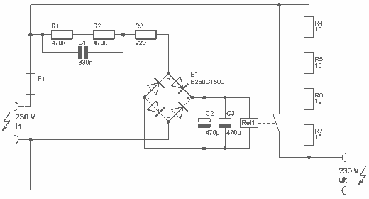
This delay can be used in power amplifiers to prevent the fuses from failing when the amplifier is turned on. The circuit is very simple with a relay that is turned on when C2 and C3 are charged. If...
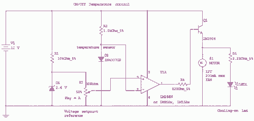
This circuit controls a load (in this case a DC brushless fan) based on a temperature compared with a setpoint. The transducer is a diode in the forward polarization regime. In fact, when forward biased, the forward voltage drop...
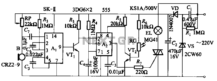
This circuit utilizes a dedicated voice integrated circuit (AI) of the SK type, which incorporates an internal bistable multivibrator and three inverting amplifiers. The 555 integrated circuit (IC) A2 is employed for delay control. The described circuit is designed to...
Analog switches alternately pass and block the input signal through a low-pass filter to create a pulsating flow smoothing effect, converting it into a direct current (DC) signal. The operational amplifier, referred to as OP Xiao Ai, functions as...
These two simple circuits provide zero voltage switching. They can be used with full wave bridges or in antiparallel to provide full wave control and are normally used to trigger power thyristors. If an input signal is present during...

This circuit was designed to control power delivery to a Peltier cooler in a vehicle. The power to the load from the vehicle's battery is managed by a Single Pole Double Throw (SPDT) relay. The circuit utilizes an SPDT relay...